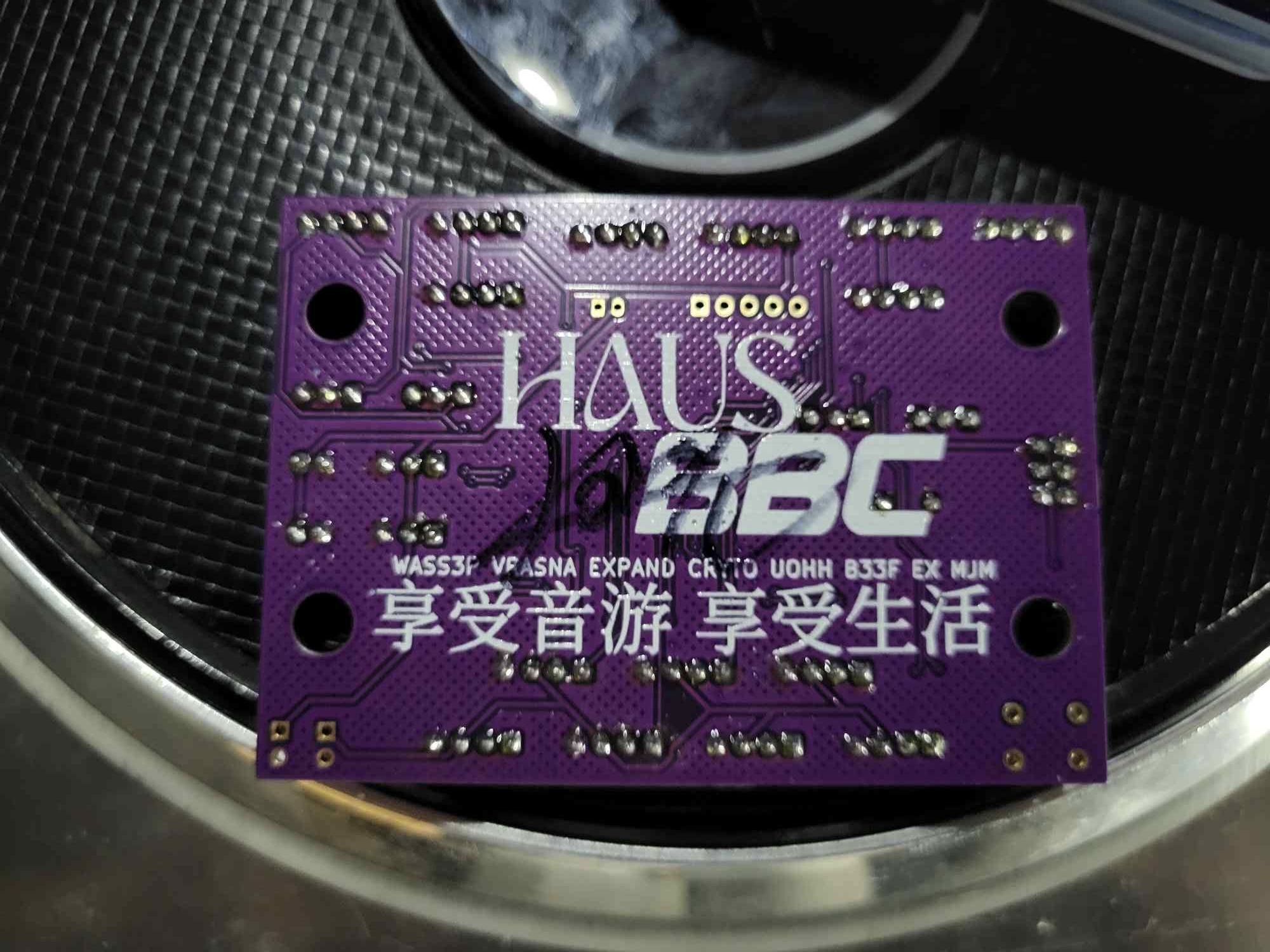
This is a USB I/O PCB for use with Konami Rhythm games. Drop-in support for PHOENIXWAN+ and FAUCETWO controllers. Games currently supported:
- Beatmania IIDX
- Sound Voltex
- Pop'n Music
IIDX
| Input | Board label |
|---|---|
| B1-7 | Obvious enough |
| E1/Start | B8 |
| E2 | B9 |
| E3 | B10 |
| E4/Select | B11 |
| TT photointerruptor 1 | DAO_E1P1 |
| TT photointerruptor 2 | DAO_E1P2 |
| TT RGB LEDs | TT_LED |
| Bar RGB LEDs | DAO_BAR |
SDVX
| Input | Board label |
|---|---|
| BT-A | B1 |
| BT-B | B2 |
| BT-C | B3 |
| BT-D | B4 |
| FX-L | B5 |
| FX-R | B6 |
| Start | B9 |
| AC-style knobs | SDVX1 and SDVX2 |
Various configuration options can be changed on-the-fly by holding a button combination. Holding the buttons simultaneously for 1 second will cause the change to take affect. Button lights will momentarily shut off to indicate that the change has occurred.
Refer to these tables for a list of configuration options currently supported:
| Configuration option | Button combination |
|---|---|
| Reverse TT direction | B1 + B7 + B8 |
| Change TT lighting effects | B2 + B8 + B11 |
| Increase TT deadzone | B7 + B8 + B11 |
| Decrease TT deadzone | B5 + B8 + B11 |
| Increase TT sensitivity | B3 + B8 + B11 |
| Decrease TT sensitivity | B1 + B8 + B11 |
| Change centre bar lighting effects (PHOENIXWAN only) | B6 + B8 + B10 |
| Disable LEDs | B4 + B8 + B11 |
| Change turntable hue | B2 + B11 + TT |
| Change turntable saturation | B4 + B11 + TT |
| Change turntable brightness | B6 + B11 + TT |
Note: TT deadzone only affects digital TT output.
| Configuration option | Button combination |
|---|---|
| Disable LEDs | B1 + B2 + B3 + B4 + B9 |
There also exist button combinations which perform special actions if held while connecting the device:
| Special action | Button combination |
|---|---|
| Enter programming mode | B1 + B2 |
| IIDX mode - HID (default) | B1 + B8 |
| IIDX mode - Keyboard | B2 + B8 |
| SDVX mode - HID | B1 + B9 |
| SDVX mode - Keyboard | B2 + B9 |
You can also use the web config tool to quickly configure multiple settings, reset settings to default values or to launch the bootloader to flash a new firmware.
### PIN HEADERS ###
1    JST XH 5pin
15   JST XH 4pin
6    JST XH 3pin
2    JST XH 2pin
1    JST PH 2pin
2    JST PH 3pin
2    1x2 2.54mm pin header
1    IDC header 2x3pin 2.54mm (optional)

### MCU ###
1    AT90USB1286 TQFP
1    16MHz crystal (ECS-160-18-4X-CKM)
11   2N7002
1    6mm push button

### CAPACITORS ###
2    1uF 0805
5    100nF 0805
2    10pF 0805

### RESISTORS ###
1    1K 0805
2    22 ohm 0805

### REMOTE BOARD ###
2   JST XH 4pin (angled)
2   USB-B (ED2983-ND)
- HW design by HWXLR8
- FW written by HWXLR8 / supervaka / ASleepyCat
- HID implementation provided by the LUFA project
- Implementation of the WS2812 protocol provided by FastLED
- kinetic-flow's arcin-infinitas for:
- RGB HID functionality
- FastLED shims
- Debounce code
- Special thanks to Mechada and Cryto for beta testing


