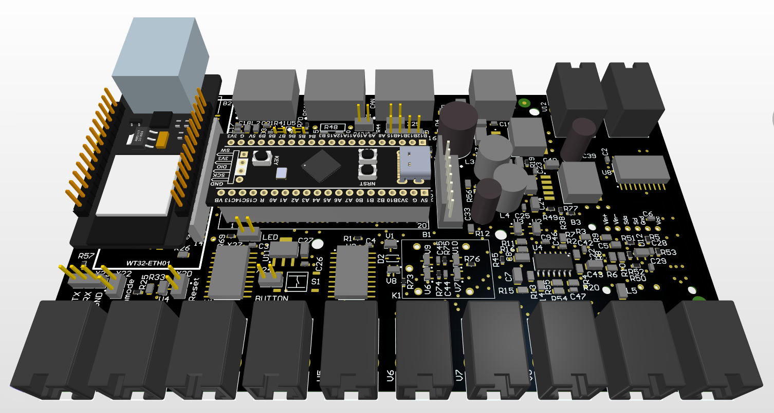
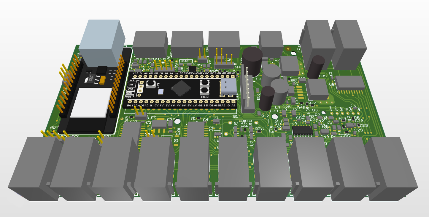
- added support for different RJ10 PCB connectors
- corrected some imprints
c3-sample/revision schematic is the same as c2-sample.
- replaced relay K1 with fet transistors
- corrected button S1 connection, a push now pulls-up STM32 pin voltage to 3V3
- added some filtering for analog signals
You can find the c2-sample/revision schematic here: schematic_c2-sample_V02.pdf
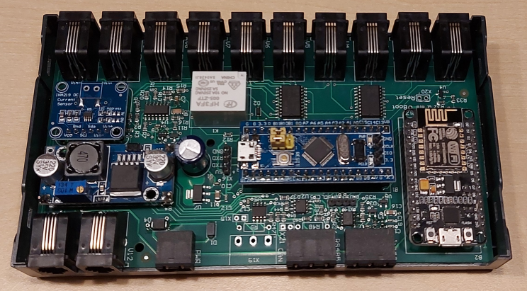
- uC STM32F401CCU on BlackPill board
- I ran out of flash on STM32F103 nor it is available as a genuine part anywhere
- WT32-ETH01 module for Ethernet (RJ45) or wifi connection
- current sensing by opamp circuit, optional INA219 current sensor
- L293 for motorcontrol
- back EMF circuit to identify a single commutator switch for counting motor revolutions
- optional CAN bus via MCP2515
- RS485
- 1-wire via discrete circuit with 3k3 pull-up
- optional via DS2482-100
- optional: I2C display (5V) or other I2C slaves
- supply voltage 10...24V
- LM2596 step-down converter integrated
- power savings: all three L293 can be switched off by software
- with only STM32 running approx. 300 mW
You can find the c-sample schematic here: schematic_c-sample_V02.pdf
- uC STM32F103C8 on BluePill board
- INA219 current sensor
- L293 for motorcontrol
- back EMF circuit to identify a single commutator switch
- many thanks to Yi Yao for his inspiration: DC Motor Controller and Tachometer
- interfaces: CAN bus, RS485
- wifi via ESP8266
- 1-wire via DS2482-100
- optional: I2C display
- supply voltage 10...24V
You can find the b-sample schematic here: schematic_b-sample_V02.pdf
BOM: b-sample BOM
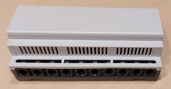
- apra Rail DB 449-370-55
- housing for 35mm DIN rail
- only small rework needed, 2 mm cutback for RJ11 needed


