This device provides the following features:
- Ability to burn a bootloader and upload code to an ATmega328 TQFP-32 device.
- 5 output pins: D0, D1, D11, D12 and D13.
To burn the bootloader and upload code, [follow these steps] (https://github.com/dsikar/arduino/tree/master/lcd-multinode-master-pidx3#notes-on-configuring-the-arduino-on-a-breadboard), changing the Due board option for Uno, basically turning the ATmega328 TQFP-32 into a feature-limited Uno, hence the name RDNO 0.
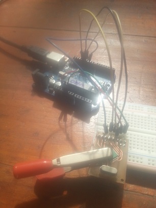
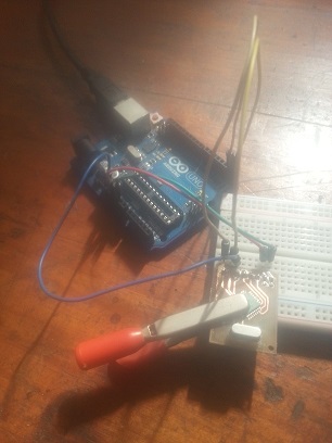
Notice that when burning the bootloader, SCK, MOSI, MISO and RESET pins need to be wired. When uploading code, the required pins are RX, TX and RESET. In both cases, Ground and +5V need to be wired.
Once the code is uploaded, you'll have a very basic Arduino in your hands, and somewhat precarious, given that the chip is secured to board with a crocodile clip, but hey, that is $1's worth of arduino goodness.
The connectors on the board, from left to right, match the SL1 connector in the schematic from top to bottom.

Burning the bootloader
Here we have SCK, MOSI, MISO, RESET, +5V and GND wired

Uploading code
RX, TX, RESET, +5V and GND wired

Blink example
SCK, +5V and GND wired, SCK (D13) wired to UNO's D13 to use the on-board LED

Bluetooth LED
D11, D12, D13, +5V and GND wired, D11 wired to LED, D11 and D12 functioning as RX and TX to [Bluetooth module] (https://github.com/dsikar/jskonit-proof-of-concept)

