The Service Fabric Cluster Resource Manager provides several mechanisms for describing a cluster. During run time, the Resource Manager uses this information to ensure high availability of the services running in the cluster while also ensuring that the resources in the cluster are being used appropriately.
The Cluster Resource Manager features that describe a cluster are:
- Fault Domains
- Upgrade Domains
- Node Properties
- Node Capacities
A fault domain is any area of coordinated failure. A single machine is a fault domain (since it alone can die for a lot of different reasons, from power supply failures to drive failures to bad NIC firmware). A bunch of machines connected to the same Ethernet switch are in the same fault domain, as would be those connected to a single source of power.
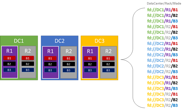
If you were setting up your own cluster you’d need to think about all of these different areas of failure and make sure that your fault domains were set up correctly so that Service Fabric would know where it was safe to place services. By “safe” we really mean smart – we don’t want to place services such that a loss of a fault domain causes the service to go down. In the Azure environment we leverage the fault domain information provided by the Azure Fabric Controller/Resource Manager in order to correctly configure the nodes in the cluster on your behalf. In the graphic below (Fig. 7) we color all of the entities that reasonably result in a fault domain as a simple example and list out all of the different fault domains that result. In this example, we have datacenters (DC), racks (R), and blades (B). Conceivably, if each blade holds more than one virtual machine, there could be another layer on the fault domain hierarchy.
During run time, the Service Fabric Cluster Resource Manager considers the fault domains in the cluster and attempts to spread out the replicas for a given service so that they are all in separate fault domains. This process helps ensure that in case of failure of any one fault domain, that the availability of that service is not compromised.
Service Fabric’s Cluster Resource Manager doesn’t really care about how many layers there are in the hierarchy, however since it does try to ensure that the loss of any one portion of the hierarchy doesn’t impact the cluster or the services running on top of it, it is generally best if at each level of depth in the fault domain there are the same number of machines. This prevents one portion of the hierarchy from having to contain more services at the end of the day than others.
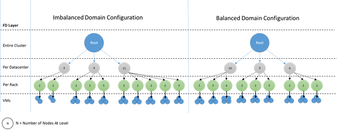
Configuring your cluster in such a way that the “tree” of fault domains is unbalanced makes it rather hard for the Resource Manager to figure out what the best allocation of replicas is, particularly since it means that the loss of a particular domain can overly impact the availability of the cluster – the Resource Manager is torn between using the machines in that “heavy” domain efficiently and placing services so that the loss of the domain doesn’t cause problems.
In the diagram below we set up two different clusters, one where the nodes are well distributed across the fault domains, and another where one fault domain ends up with many more nodes. Note that in Azure the choices about which nodes end up in which fault and upgrade domains is handled for you, so you should never see these sorts of imbalances. However, if you ever stand up your own cluster on-premise or in another environment, it’s something you have to think about.
Upgrade Domains are another feature that helps the Service Fabric Resource Manager to understand the layout of the cluster so that it can plan ahead for failures. Upgrade Domains define areas (sets of nodes, really) that will go down at the same time during an upgrade.
Upgrade Domains are a lot like Fault Domains, but with a couple key differences. First, Upgrade Domains are usually defined by policy; whereas Fault Domains are rigorously defined by the areas of coordinated failures (and hence usually the hardware layout of the environment). In the case of Upgrade Domains however you get to decide how many you want. Another difference is that (today at least) Upgrade Domains are not hierarchical – they are more like a simple tag than a hierarchy.
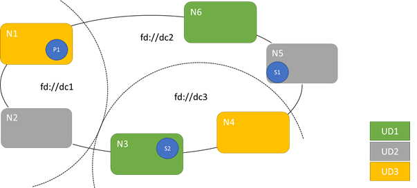
The picture below shows a fictional setup where we have three upgrade domains striped across three fault domains. It also shows one possible placement for three different replicas of a stateful service. Note that they are all in different fault and upgrade domains. This means that we could lose a fault domain while in the middle of a service upgrade and there would still be one running copy of the code and data in the cluster. Depending on your needs this could be good enough, however you may notice though that this copy could be old (as Service Fabric uses quorum based replication). In order to truly survive two failures you’d need more replicas (five at a minimum).
There are pros and cons to having large numbers of upgrade domains – the pro is that each step of the upgrade is more granular and therefore affects a smaller number of nodes or services. This results in fewer services having to move at a time, introducing less churn into the system and overall improving reliability (since less of the service will be impacted by any issue). The downside of having many upgrade domains is that Service Fabric verifies the health of each Upgrade Domain as it is upgraded and ensures that the Upgrade Domain is healthy before moving on to the next Upgrade Domain. The goal of this check is to ensure that services have a chance to stabilize and that their health is validated before the upgrade proceeds, so that any issues are detected. The tradeoff is acceptable because it prevents bad changes from affecting too much of the service at a time.
Too few upgrade domains has its own side effects – while each individual upgrade domain is down and being upgraded a large portion of your overall capacity is unavailable. For example, if you only have three upgrade domains you are taking down about 1/3 of your overall service or cluster capacity at a time. This isn’t desirable as you have to have enough capacity in the rest of your cluster to cover the workload, meaning that in the normal case those nodes are less-loaded than they would otherwise be, increasing COGS.
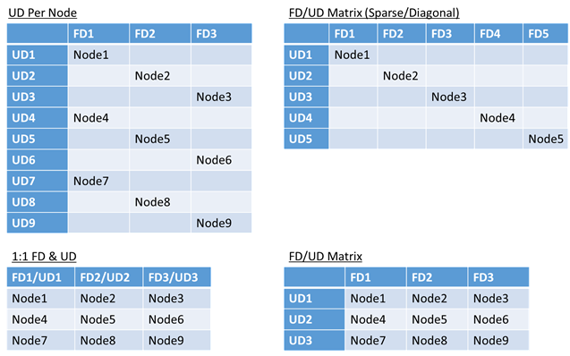
There’s no real limit to the total number of fault or upgrade domains in an environment, or constraints on how they overlap. Common structures that we’ve seen are 1:1 (where each unique fault domain maps to its own upgrade domain as well), an Upgrade Domain per Node (physical or virtual OS instance), and a “striped” or “matrix” model where the Fault Domains and Upgrade Domains form a matrix with machines usually running down the diagonal.
There’s no best answer which layout to choose, each has some pros and cons. For example, the 1FD:1UD model is fairly simple to set up, whereas the 1 UD per Node model is most like what people are used to from managing small sets of machines in the past where each would be taken down independently.
The most common model (and the one that we use for the hosted Azure Service Fabric clusters) is the FD/UD matrix, where the FDs and UDs form a table and nodes are placed starting along the diagonal. Whether this ends up sparse or packed depends on the total number of nodes compared to the number of FDs and UDs (put differently, for sufficiently large clusters, almost everything ends up looking like the dense matrix pattern, shown in the bottom right option of Figure 10).
Defining Fault Domains and Upgrade Domains is done automatically in Azure hosted Service Fabric deployments; Service Fabric just picks up the environment information from Azure. In turn you the User can pick the number of domains you want. In Azure both the fault and upgrade domain information looks “single level” but it really is encapsulating information from lower layers of the Azure stack and just presenting the logical fault and upgrade domains from the user’s perspective.
If you’re standing up your own cluster (or just want to try running a particular topology on your development machine) you’ll need to provide the fault domain and upgrade domain information yourself. In this example we define a 9 node cluster that spans three “datacenters” (each with three racks), and three upgrade domains striped across those three datacenters. In your cluster manifest, it looks something like this:
ClusterManifest.xml
  <Infrastructure>
    <!-- IsScaleMin indicates that this cluster runs on one-box /one single server -->
    <WindowsServer IsScaleMin="true">
      <NodeList>
        <Node NodeName="Node01" IPAddressOrFQDN="localhost" NodeTypeRef="NodeType01" FaultDomain="fd:/DC01/Rack01" UpgradeDomain="UpgradeDomain1" IsSeedNode="true" />
        <Node NodeName="Node02" IPAddressOrFQDN="localhost" NodeTypeRef="NodeType02" FaultDomain="fd:/DC01/Rack02" UpgradeDomain="UpgradeDomain2" IsSeedNode="true" />
        <Node NodeName="Node03" IPAddressOrFQDN="localhost" NodeTypeRef="NodeType03" FaultDomain="fd:/DC01/Rack03" UpgradeDomain="UpgradeDomain3" IsSeedNode="true" />
        <Node NodeName="Node04" IPAddressOrFQDN="localhost" NodeTypeRef="NodeType04" FaultDomain="fd:/DC02/Rack01" UpgradeDomain="UpgradeDomain1" IsSeedNode="true" />
        <Node NodeName="Node05" IPAddressOrFQDN="localhost" NodeTypeRef="NodeType05" FaultDomain="fd:/DC02/Rack02" UpgradeDomain="UpgradeDomain2" IsSeedNode="true" />
        <Node NodeName="Node06" IPAddressOrFQDN="localhost" NodeTypeRef="NodeType06" FaultDomain="fd:/DC02/Rack03" UpgradeDomain="UpgradeDomain3" IsSeedNode="true" />
        <Node NodeName="Node07" IPAddressOrFQDN="localhost" NodeTypeRef="NodeType07" FaultDomain="fd:/DC03/Rack01" UpgradeDomain="UpgradeDomain1" IsSeedNode="true" />
        <Node NodeName="Node08" IPAddressOrFQDN="localhost" NodeTypeRef="NodeType08" FaultDomain="fd:/DC03/Rack02" UpgradeDomain="UpgradeDomain2" IsSeedNode="true" />
        <Node NodeName="Node09" IPAddressOrFQDN="localhost" NodeTypeRef="NodeType09" FaultDomain="fd:/DC03/Rack03" UpgradeDomain="UpgradeDomain3" IsSeedNode="true" />
      </NodeList>
    </WindowsServer>
  </Infrastructure>
[AZURE.NOTE] In Azure deployments, fault domains and upgrade domains are assigned by Azure. Therefore, the definition of your nodes and roles within the infrastructure option for Azure does not include fault domain or upgrade domain information.
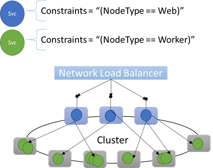
Sometimes (in fact, most of the time) you’re going to want to ensure that certain workloads run only on certain nodes or certain sets of nodes. For example, some workload may require GPUs or SSDs while others may not. A great example of this is pretty much every n-tier architecture out there, where certain machines serve as the front end/interface serving side of the application while a different set (often with different hardware resources) handle the work of the compute or storage layers. Service Fabric expects that even in a microservices world there are cases where particular workloads will need to run on particular hardware configurations, for example:
- an existing n-tier application has been “lifted and shifted” into a Service Fabric environment
- a workload wants to run on specific hardware for performance, scale, or security isolation reasons
- A workload needs to be isolated from other workloads for policy or resource consumption reasons
In order to support these sorts of configurations Service Fabric has a first class notion of what we call placement constraints. Constraints can be used to indicate where certain services should run. The set of constraints is extensible by users, meaning that people can tag nodes with custom properties and then select for those as well.
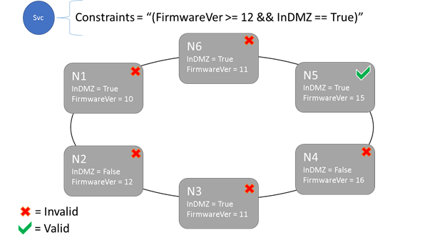
The different key/value tags on nodes are known as node placement properties (or just node properties), whereas the statement at the service is called a placement constraint. The value specified in the node property can be a string, bool, or signed long. The constraint can be any Boolean statement that operates on the different node properties in the cluster, and only nodes where the statement evaluates to “True” can have the service placed on it. Nodes without a property defined do not match any placement constraint that contains that property. Service Fabric also defines some default properties which can be used automatically without the user having to define them. As of this writing the default properties defined at each node are the NodeType and the NodeName. Generally we have found NodeType to be one of the most commonly used properties, as it usually corresponds 1:1 with a type of a machine, which in turn correspond to a type of workload in a traditional n-tier application architecture.
Let’s say that the following node properties were defined for a given node type: ClusterManifest.xml
    <NodeType Name="NodeType01">
      <PlacementProperties>
        <Property Name="HasDisk" Value="true"/>
        <Property Name="Value" Value="5"/>
      </PlacementProperties>
    </NodeType>
You can create service placement constraints for a service like this:
C#
FabricClient fabricClient = new FabricClient();
StatefulServiceDescription serviceDescription = new StatefulServiceDescription();
serviceDescription.PlacementConstraints = "(HasDisk == true && Value >= 4)";
// add other required servicedescription fields
//...
await fabricClient.ServiceManager.CreateServiceAsync(serviceDescription);
Powershell:
New-ServiceFabricService -ApplicationName $applicationName -ServiceName $serviceName -ServiceTypeName $serviceType -Stateful -MinReplicaSetSize 2 -TargetReplicaSetSize 3 -PartitionSchemeSingleton -PlacementConstraint "HasDisk == true && Value >= 4"If you are sure that all nodes of NodeType01 are valid, you could also just select that node type, using placement constraints like those show in the pictures above.
One of the cool things about a service’s placement constraints is that they can be updated dynamically during runtime. So if you need to, you can move a service around in the cluster, add and remove requirements, etc. Service Fabric takes care of ensuring that the service stays up and available even when these types of changes are ongoing.
C#:
StatefulServiceUpdateDescription updateDescription = new StatefulServiceUpdateDescription();
updateDescription.PlacementConstraints = "NodeType == NodeType01";
await fabricClient.ServiceManager.UpdateServiceAsync(new Uri("fabric:/app/service"), updateDescription);
Powershell:
Update-ServiceFabricService -Stateful -ServiceName $serviceName -PlacementConstraints "NodeType == NodeType01"Placement constraints (along with many other properties that we’re going to talk about) are specified for every different service instance. Updates always take the place (overwrite) what was previously specified.
It is also worth noting that at this point the properties on a node are defined via the cluster definition and hence cannot be updated without an upgrade to the cluster.
One of the most important jobs of any orchestrator is to help manage resource consumption in the cluster. The last thing you want if you’re trying to run services efficiently is a bunch of nodes which are hot (leading to resource contention and poor performance) while others are cold (wasted resources). But let’s think even more basic than balancing (which we’ll get to in a minute) – what about just ensuring that nodes don’t run out of resources in the first place?
It turns out that Service Fabric represents resources as things called “Metrics”. Metrics are any logical or physical resource that you want to describe to Service Fabric. Examples of metrics are things like “WorkQueueDepth” or “MemoryInMb”. Metrics are different from constraints and node properties in that node properties are generally static descriptors of the nodes themselves, whereas metrics are about physical resources that services consume when they are running on a node. So a property would be something like HasSSD and could be set to true or false, but the amount of space available on that SSD (and consumed by services) would be a metric like “DriveSpaceInMb”. Capacity on the node would set the “DriveSpaceInMb” to the amount of total non-reserved space on the drive, and services would report how much of the metric they used during runtime.
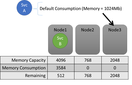
If you turned off all resource balancing Service Fabric’s Resource Manager would still be able to ensure that no node ended up over its capacity (unless the cluster as a whole was too full). Capacities are the mechanism that Service Fabric uses to understand how much of a resource a node has, from which we subtract consumption by different services (more on that later) in order to know how much is left. Both the capacity and the consumption at the service level are expressed in terms of metrics.
During runtime, the Resource Manager tracks how much of each resource is present on each node (defined by its capacity) and how much is remaining (by subtracting any declared usage from each service). With this information, the Service Fabric Resource Manager can figure out where to place or move replicas so that nodes don’t go over capacity.
C#:
StatefulServiceDescription serviceDescription = new StatefulServiceDescription();
ServiceLoadMetricDescription metric = new ServiceLoadMetricDescription();
metric.Name = "Memory";
metric.PrimaryDefaultLoad = 1024;
metric.SecondaryDefaultLoad = 1024;
metric.Weight = ServiceLoadMetricWeight.High;
serviceDescription.Metrics.Add(metric);
await fabricClient.ServiceManager.CreateServiceAsync(serviceDescription);
Powershell:
New-ServiceFabricService -ApplicationName $applicationName -ServiceName $serviceName -ServiceTypeName $serviceTypeName –Stateful -MinReplicaSetSize 2 -TargetReplicaSetSize 3 -PartitionSchemeSingleton –Metric @("Memory,High,1024,1024”)You can see these in the cluster manifest:
ClusterManifest.xml
    <NodeType Name="NodeType02">
      <Capacities>
        <Capacity Name="Memory" Value="10"/>
        <Capacity Name="Disk" Value="10000"/>
      </Capacities>
    </NodeType>
It is also possible that a service’s load changes dynamically. In this case it’s possible that where a replica or instance is currently placed becomes invalid since the combined usage of all of the replicas and instances on that node exceeds that node’s capacity. We’ll talk more about this scenario where load can change dynamically later, but as far as capacity goes it is handled the same way – Service Fabric resource management automatically kicks in and gets the node back below capacity by moving one or more of the replicas or instances on that node to different nodes. When doing this the Resource Manager tries to minimize the cost of all of the movements (we’ll come back to the notion of Cost later).
So how do we keep the overall cluster from being too full? Well, with dynamic load there’s actually not a lot we can do (since services can have their load spike independent of actions taken by the Resource Manager – your cluster with a lot of headroom today may be rather underpowered when you become famous tomorrow), but there are some controls that are baked in to prevent basic errors. The first thing we can do is prevent the creation of new workloads that would cause the cluster to become full.
Say that you go to create a simple stateless service and it has some load associated with it (more on default and dynamic load reporting later). For this service, let’s say that it cares about some resource (let’s say DiskSpace) and that by default it is going to consume 5 units of DiskSpace for every instance of the service. You want to create 3 instances of the service. Great! So that means that we need 15 units of DiskSpace to be present in the cluster in order for us to even be able to create these service instances. Service Fabric is continually calculating the overall capacity and consumption of each metric, so we can easily make the determination and reject the create service call if there’s insufficient space.
Note that since the requirement is only that there be 15 units available, this space could be allocated many different ways; it could be one remaining unit of capacity on 15 different nodes, for example, or three remaining units of capacity on 5 different nodes, etc. If there isn’t sufficient capacity on three different nodes Service Fabric will reorganize the services already in the cluster in order to make room on the three necessary nodes. Such rearrangement is almost always possible unless the cluster as a whole is almost entirely full.
Another thing we did that helped people manage overall cluster capacity was to add the notion of some reserved buffer to the capacity specified at each node. This setting is optional, but allows people to reserve some portion of the overall node capacity so that it is only used to place services during upgrades and failures – cases where the capacity of the cluster is otherwise reduced. Today buffer is specified globally per metric for all nodes via the ClusterManifest. The value you pick for the reserved capacity will be a function of which resources your services are more constrained on, as well as the number of fault and upgrade domains you have in the cluster. Generally more fault and upgrade domains means that you can pick a lower number for your buffered capacity, as you will expect smaller amounts of your cluster to be unavailable during upgrades and failures. Note that specifying the buffer percentage only makes sense if you have also specified the node capacity for a metric.
ClusterManifest.xml
        <Section Name="NodeBufferPercentage">
            <Parameter Name="DiskSpace" Value="0.10" />
            <Parameter Name="Memory" Value="0.15" />
            <Parameter Name="SomeOtherMetric" Value="0.20" />
        </Section>
Creation calls resulting in new services fail when the cluster is out of buffered capacity, ensuring that the cluster retains enough spare overhead such that upgrades and failures don’t result in nodes being actually over capacity. The Resource Manager exposes a lot of this information via PowerShell and the Query APIs, letting you see the buffered capacity settings, the total capacity, and the current consumption for every given metric. Here we see an example of that output:
PS C:\Users\user> Get-ServiceFabricClusterLoadInformation
LastBalancingStartTimeUtc : 9/1/2015 12:54:59 AM
LastBalancingEndTimeUtc   : 9/1/2015 12:54:59 AM
LoadMetricInformation     :
                            LoadMetricName        : Metric1
                            IsBalancedBefore      : False
                            IsBalancedAfter       : False
                            DeviationBefore       : 0.192450089729875
                            DeviationAfter        : 0.192450089729875
                            BalancingThreshold    : 1
                            Action                : NoActionNeeded
                            ActivityThreshold     : 0
                            ClusterCapacity       : 189
                            ClusterLoad           : 45
                            ClusterRemainingCapacity : 144
                            NodeBufferPercentage  : 10
                            ClusterBufferedCapacity : 170
                            ClusterRemainingBufferedCapacity : 125
                            ClusterCapacityViolation : False
                            MinNodeLoadValue      : 0
                            MinNodeLoadNodeId     : 3ea71e8e01f4b0999b121abcbf27d74d
                            MaxNodeLoadValue      : 15
MaxNodeLoadNodeId : 2cc648b6770be1bc9824fa995d5b68b1- For information on the architecture and information flow within the Cluster Resource manager, check out this article
- Defining Defragmentation Metrics is one way to consolidate load on nodes instead of spreading it out. To learn how to configure defragmentation, refer to this article
- Start from the beginning and get an Introduction to the Service Fabric Cluster Resource Manager
- To find out about how the Cluster Resource Manager manages and balances load in the cluster, check out the article on balancing load
