Notes on Arduino libraries and sketches and other related stuff.
- My Libraries and projects
- Sketches
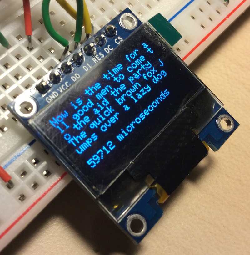
- Interfacing SSD1306 based OLED displays (SPI)
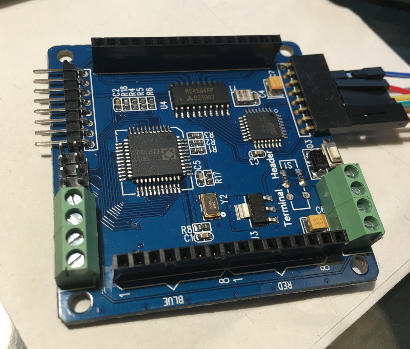
- Colorduino RGB matrix driver
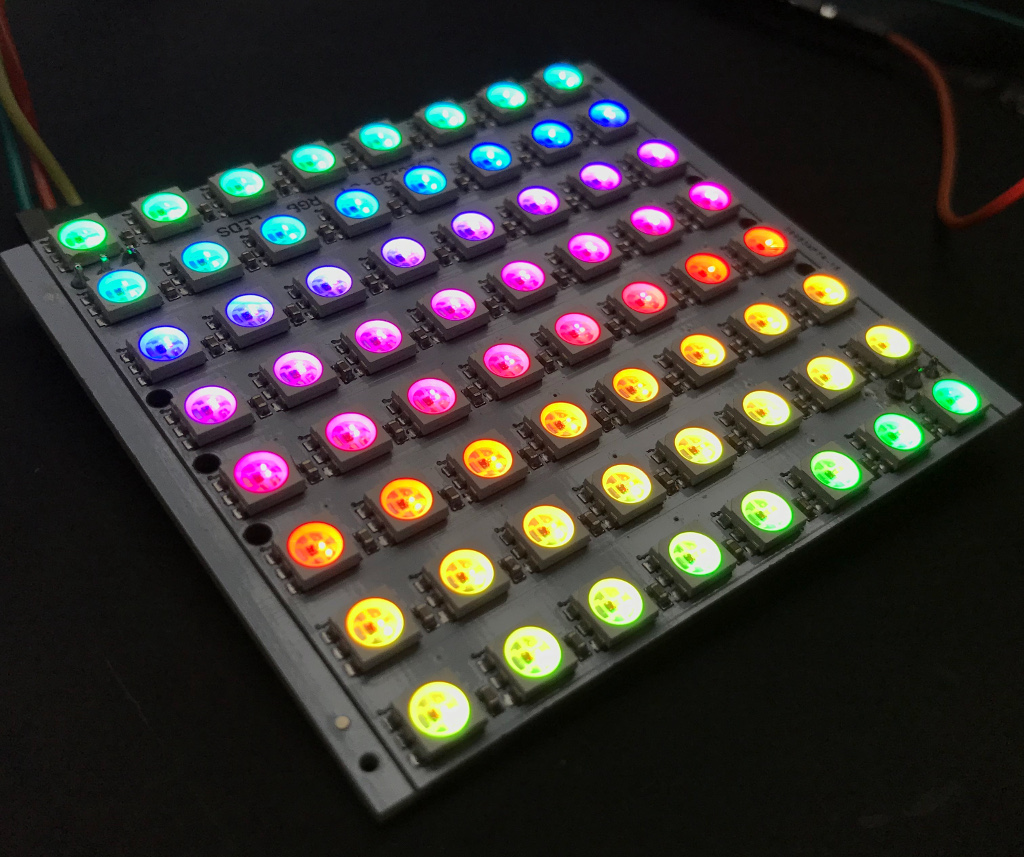
- CJMCU-8x8 RGB matix
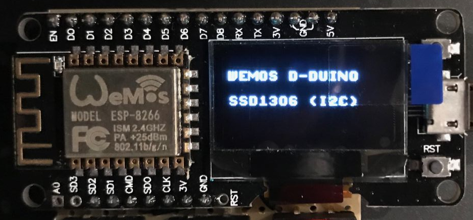
- WEMOS D-Duino
- ESP32 TTGO
- Heltec WiFi Lora 32
- Raspberry Pi 480x320 SPI TFT Display (3.5 inches)
- Sipeed Longan Nano RISC-V proto board (GD32VF103CBT6)
- Raspberry Pi HDMI LCD display (800x480, 4")
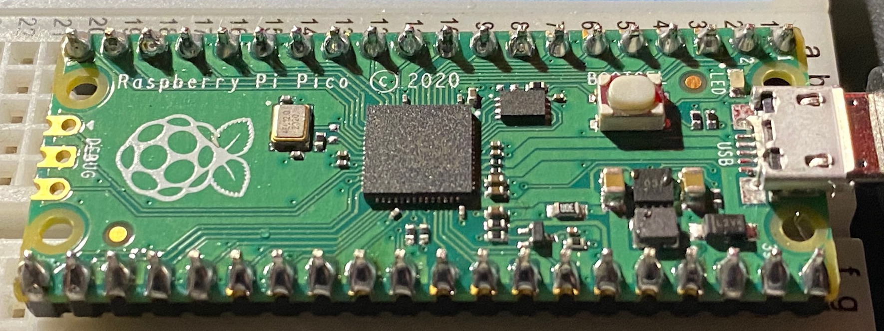
- Raspberry Pi Pico (RP2040)
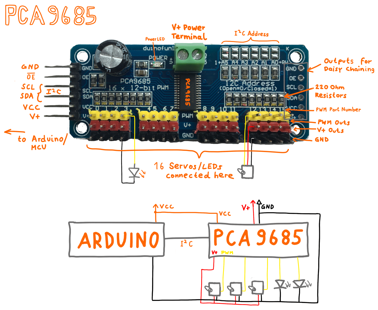
- PCA9685 driver board
- MP3 Modules
- Bosch BMP280
- TM1637 based Display
- Misc
- Author
JLed is an Arduino library to control LEDs. It uses a non-blocking approach and can control LEDs in simple (on/off) and complex (blinking, breathing) ways in a time-driven manner. It's available as a C++ or Python lib.
// breathe LED (on gpio 9) 6 times for 1500ms, waiting for 500ms after each run
#include <jled.h>

auto led_breathe = JLed(9).Breathe(1500).Repeat(6).DelayAfter(500);

void setup() { }

void loop() {
  led_breathe.Update();
}
The Python API mirrors the C++ API:
import board
from jled import JLed

led = JLed(board.LED).blink(500, 500).forever()

while True:
led.update()A lightweight, no-frills logging library for Arduino & friends.
LOG("hello, log4arduino.");
delay(42);
LOG("use %s formatting: %d %c %d %c %d", "printf", 9, '+', 1, '=', 10);
Allows simple printf-like formatting and shows current time in millis and available memory, e.g.
0(1623): hello, log4arduino.
42(1609): use printf formatting: 9 + 1 = 10
Code, tools and instructions on how to connect ESP32 securely to the AWS IOT cloud.
An Arduino Pro Micro based USB spinner (like a paddle) game controller. Great to play games like e.g. Arkanoid. Simulates an USB mouse and needs no drivers.
Simulates an USB mouse using an Attiny85 (Digispark board) and randomly moves your mouse (see The Simpsons S07E07).
To build the demo sketches you can either copy the folders to the source folder of your Arduino IDE or use PlatformIO and the provided makefiles, e.g.:
$ cd cjmcu_8x8_sample
$ make upload
The following make targets can be used: run, envdump, clean, upload, monitor
- ssd1306_sample_adafruit - sample code for ssd1306 based oled display. see wiki for detailed information
- ssd1306_sample_u8g - sample code for ssd1306 based oled display. see wiki for detailed information
Driver for 8x8 RGB LED matrix.
- see wiki for detailed information
An 8x8 LED RGB matrix based on WS2812 "NeoPixels".
- see README of example sketch for detailed info rmation.
The Wemos D-Duino is an ESP8266 board with an integrated SSD1306 OLED display connected via I2C.
- SSD1306 is connected with I2C and SCL connected to D2 and SDA connected to D1.
- see example sketch for an example on how to use it with the u8g2 library.
The ESP32 TTGO is an EPS32 with an integrated SSD1306 OLED display connected via I2C. The board also has a 18650 battery holder on the back, and and on-off switch.
- SSD1306 is connected with I2C and SCL connected to GPIO4 and SDA connected to GPIO5.
- the builtin blue LED is connected to GPIO 16
- see example sketch for an example on how to use it with the u8g2 library.
The Heltec Wifi Lora 32 is an ESP32 board with a builtin OLED display and LORA transceiver.
- the builtin LED is connected to
GPIO 25(e.g. usedigitalWrite(25, 255)) - OLED: u8glib configuration
U8X8_SSD1306_128X64_NONAME_SW_I2C u8x8(/* clock=*/ 15, /* data=*/ 4, /* reset=*/ 16); - see example sketch for an example on how to use the OLED
- TODO will add Lora example later ...
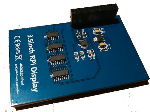
The display is labeled with RPi Display 480x320 Pixel XPT246 Touch Controller
and uses an ILI9486 controller. In raspian (tested with 2018-11-13 Raspian).
no additional drivers are needed. I got it running with the following configuration:
Add to /boot/config.txt:
dtparam=spi=on
dtoverlay=piscreen,speed=16000000,rotate=270,fps=20
(note that the 20 fps are not reached), After reboot, check with dmesg that
the driver was loaded (framebuffer and touchscreen):
 12.814215] ads7846 spi0.1: touchscreen, irq 169
[   12.815503] input: ADS7846 Touchscreen as /devices/platform/soc/3f204000.spi/spi_master/spi0/spi0.1/input/input0
[   12.839795] fbtft: module is from the staging directory, the quality is unknown, you have been warned.
[   12.852267] fb_ili9486: module is from the staging directory, the quality is unknown, you have been warned.
[   12.853073] fbtft_of_value: regwidth = 16
[   12.853083] fbtft_of_value: buswidth = 8
[   12.853092] fbtft_of_value: debug = 0
[   12.853098] fbtft_of_value: rotate = 90
[   12.853105] fbtft_of_value: fps = 20
...
[   13.613788] graphics fb1: fb_ili9486 frame buffer, 480x320, 300 KiB video memory, 4 KiB buffer memory, fps=20, spi0.0 at 16 MHz
Test the display by loading an image using the fbi tool:
$ sudo fbi -noverbose -T 1 -a -d /dev/fb1 image-test.gif
(sudo is needed when command is run from ssh session).
Start X11 on the framebuffer with sudo FBDEV=/dev/fb1 startx.
- http://ozzmaker.com/piscreen-driver-install-instructions-2/
- Adafruit info on FPS and SPI speed
- RPi case used: https://www.thingiverse.com/thing:1229473
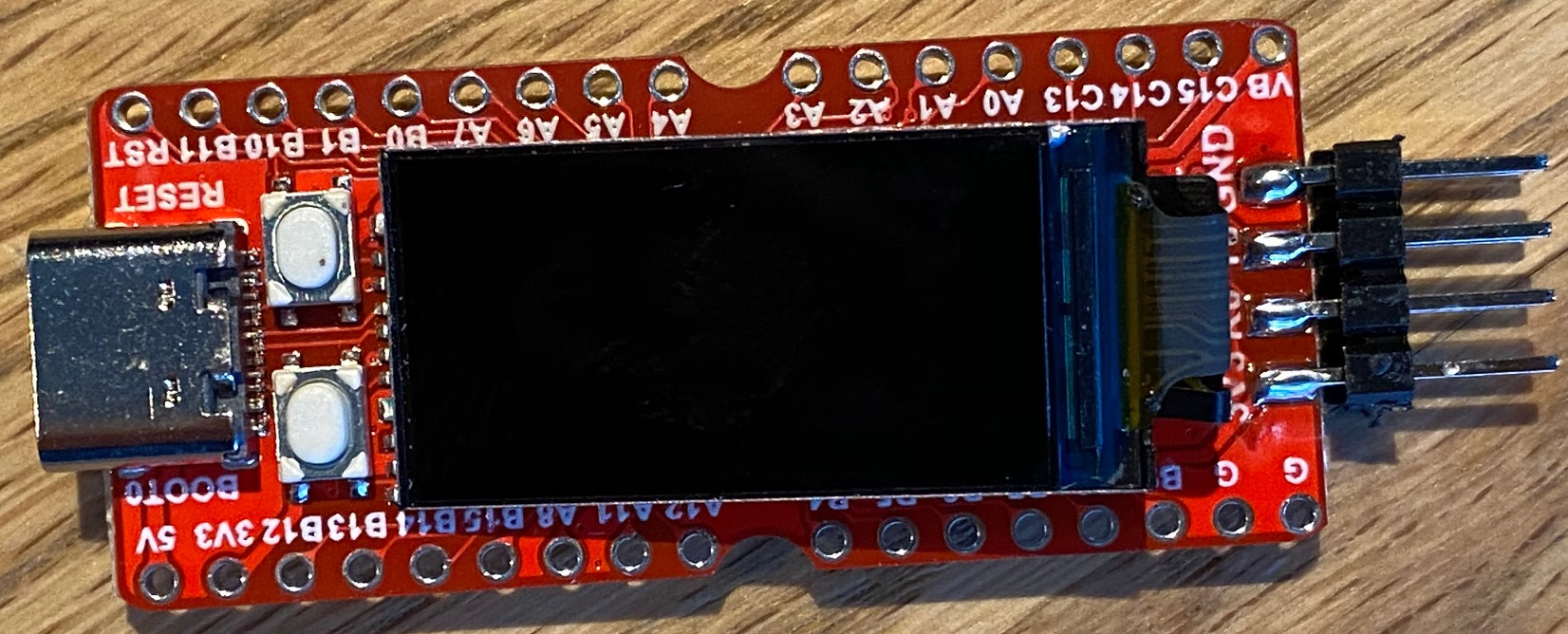
The Sipeed Longan Nano GD32VF103CBT6 board hosts a 32-bit RISC-V cpu with 32KB of SRAM and 128KB of Flash and a 160x80 Pixel RGB LCD display.
To upload a firmware image to the MCU, it has to be put into DFU mode first:
Press and hold Boot before connecting the board using USB. Alternatively when
the board is already connected: Press and hold boot and then reset to put
the board in DFU mode, otherwise no upload is possible.
Check with lsusb|grep GD32 if the board was successfully detected, the output
should look like:
Bus 001 Device 007: ID 28e9:0189 GDMicroelectronics GD32 0x418 DFU Bootloader
Running sudo dfu-util -l yields:
dfu-util 0.9
...
Found DFU: [28e9:0189] ver=1000, devnum=7, cfg=1, intf=0, path="1-2", alt=1, name="@Option Bytes  /0x1FFFF800/01*016 g", serial="??"
Found DFU: [28e9:0189] ver=1000, devnum=7, cfg=1, intf=0, path="1-2", alt=0, name="@Internal Flash  /0x08000000/512*002Kg", serial="??"
Before uploading to the MCU, make sure you installed the udev rules as described here. Afterwards a
udevadm control --reload-rules && udevadm trigger (as root) might be necessary.
The demo sketch can be compiled
and uploaded with make upload, after the board was set to DFU mode. The
following error seems to have no effect, and can be ignored:
dfu-util: dfuse_download: libusb_control_transfer returned -1
*** [upload] Error 74
If the demo sketch works, you should now see the builtin LEDs cycle in colors red, green and blue.
TODO
- LCD demo w/ arduino framework
- JLed demo
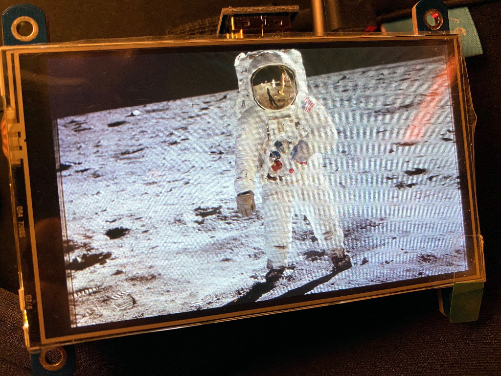
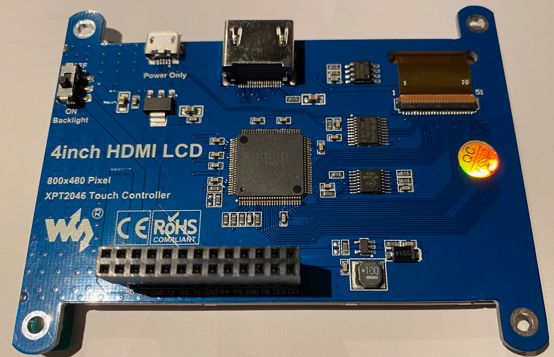
The display is labelled "4inch HDMI LCD". The resolution is 800x480 and the display has a built in XPT2046 touch controller.
I had to power both the Raspi (RPi 3) and the display to get it run. The display
needs a custom resolution in /boot/config.txt, which is set by hdmi_mode=87
and hdmi_cvt.
Add to /boot/config.txt:
framebuffer_width=800
framebuffer_height=480

hdmi_group=2
hdmi_mode=87
hdmi_cvt=480 800 60 6
display_hdmi_rotate=3
- Test the touch controller
The Raspberry Pi Pico is a cheap but powerful new (end of 2020) micro controller. It features a dual core Arm cortex M0+ processor running with up to 133Mhz, 264Kb SRAM and 2MB flash memory. It has no WiFi or Bluetooth.
To flash the Pico, press the BOOTSEL button and attach the Pico using USB to
your PC. The Pico will now act mass storage USB device. Simply copy the
firmware (uf2 extension) to the drive. The Pico will automatically disconnect
and reboot.
The Raspberry Pi Pico can be programmed in C/C++ or MicroPython. For C/C++ the pico-sdk and CMake must be used, which is not as easy to use as e.g. the Arduino IDE or platformio. To make things easier, I have created a docker image and a simple build script.
The PCA9685 is an I2C bus controlled LED/Servo controller with 16 individually controllable PWM channels. Each channel has a resolution of 12 bits, resulting in 4096 steps. All channels operate at the same fixed frequency, which must be in the range between 24Hz and 1526Hz.
The board operates at 3V to 5V, which is fed through the VCC pin. The V+ pin is optional and is used to power servos or LEDs with up to 6V. The V+ voltage can also be fed through the green terminal block and is routed to the red V+ pins.
Each of the yellow PWM outputs on the board has a 220 Ohms resistor in series, which allows the direct connection of a LED. The output level is the same as VCC.
SDA and SCL are the I2C data and clock pins. The OE pin is optional (and pulled down by default) and is used to quickly disable all outputs (by setting OE to high level).
The I2C address is by default 0x40 and can be changed by closing the A0 to
A5 pins using a soldering iron.
There are many libraries for PCA9685 based boards out there, I successfully used the Adafruit PWM Servo Driver library. Have a look at this example here.
I recently built a Music Box for Kids and evaluated some MP3 modules to find the right one for the job (I finally ended up using the DFPlayer Mini).
| WTV020M01 V1.00 | DFPlayer Mini | Catalex Serial MP3 Player V1.0 | VS1053 MP3 Shield (geeetech) | GPD2856A based | |
|---|---|---|---|---|---|
| Dimensions (mm) | 22x17 | 20x20 | 40x23 | 55x55 | 45x35, 22x34 |
| VCC | 3.3V | 3.2V-5V | 3.2V-5.2V | 3.7V-5V | |
| Chip | ? | ? | YX5300 | VLSI VS1053B | GPOD2856A |
| Media | Micro SD, 1 or 2GB, very picky | Micro SD up to 32GB | Micro SD up to GB | Micro SD | |
| Filesystem | FAT16/32 | FAT16/32 | FAT16/32 | FAT16/32 | |
| Max Files | 512 | 100*255 | ? | ? | ? |
| Formats | AD4,NO MP3 | MP3, WAV | MP3, WAV | MP1, MP2, MP3, MP4, AAC, OGG, WAV and more | |
| Frequency | 32kHz | 8-48kHz | 11-48kHz | ||
| Amplifier | Yes | Yes | Line out only | 2W Mono | |
| Buttons | Opt.: Play, Prev, Next, Vol+, Vol- | Optional | No | Play, Prev, Next, Vol+, Vol- | |
| Serial Interface | 2 Line + CLK | UART 9600bps | UART 9600bps | ||
| Microphone | No | No | No | Record in OGG, WAV | |
| Misc | Busy signal, Reset input | Busy signal, Equalizer | |||
| Price (04/2021) | ca. 4€ | Starting at 1€ | ca. 2€ | ? | starting at 1€ |
| Library | Link | Link | Link | n/a | |
| Site | |||||
| Comment | Better use DFPlayer Mini instead | Small, reliable w/ Amplifier | Many features, good documentation | Standalone Player, w/ and wo/ buttons and terminals |
Summary:
- WTV020M01 is not recommended since not supporting MP3 format and very restrictive regarding SD cards used and audio encoding
- The GPD2856A based boards are designed as stand alone players and are not meant to be controlled by a micro controller.
- The DFPlayer Mini is a reliable board which can be controlled by a micro controller. It has an amplifier built in as well as an equalizer.
- The VL1053 based shield supports many file formats and even recording of audio. It lacks an amplifier but is otherwise feature-packed.
- The Catalex board is very simple to use and can be controlled by a micro controller. It lacks an amplifier and offers only a serial interface for control.
Addiontial links:
- DFPlayerMini: https://wiki.dfrobot.com/DFPlayer_Mini_SKU_DFR0299
- Catalex: http://geekmatic.in.ua/pdf/Catalex_MP3_board.pdf
- GPD2856A: https://www.petervis.com/Electronics_Kits/gpd2856a/gpd2856a-mp3-decoder-board.html
- WTV020M01: https://hackaday.io/project/3508-portable-trollmaster-3000/log/12391-the-joy-of-using-an-underdocumented-module-and-using-a-plan-b-at-the-last-minute
- Geeetch VS1053: http://www.geeetech.com/wiki/index.php/Arduino_MP3_shield_board_with_TF_card
- Profiles for the VS1053: http://www.vlsi.fi/en/support/software/vs10xxapplications.html
The module is also capable to record audio on the SD card in OGG Vorbis and WAV
format. To encode the audio in OGG format, a plugin needs to be loaded from the
SD card. The plugins are available here at
VLSI.
Pick yours from the profiles/ directory (files with .img extension). The
name of the plugin is passed to the prepareRecordingOgg function. I had to
change the name to conform to 8.3 naming (e.g. v08k1q06.img), otherwise the
plugin did not load. Refer to the
documentation
for more details.
Libraries and examples:
- https://github.com/adafruit/Adafruit_VS1053_Library
- https://github.com/madsci1016/Sparkfun-MP3-Player-Shield-Arduino-Library
The Bosch
BMP280
is an environmental sensor, capable of measuring temperature and barometric air
Pressure. The sensor supports both I²C and SPI. There are many different
boards available, mine is labeled GY-BME/PM280 and costs about 1.60€
(02/2023). I successfully connected it using I²C and CircuitPython, running on
an Raspberry Pi Pico W using the
adafruit_bmp280
library (install on the Pico Pi with circup adadfruit_bmp280).
In the example I connected the sensor as follows:
| GY-BME/PM280 | Pico Pi Signal | Pin |
|---|---|---|
| VCC | 3V3(OUT) | 36 |
| GND | GND | 23 |
| SCL | GP17/I2C0SCL | 22 |
| SDA | GP16/I2C0SDA | 21 |
Running an I²C bus scan in the CircuitPython REPL reveals that the device is has address 0x76 (118):
>>> import busio
>>> import board
>>> i2c = busio.I2C(board.GP1, board.GP0)
>>> i2c.try_lock()
True
>>> i2c.scan()
[118]
This is important, since the Adafruit library defaults to 119. Reading values from the sensor is straight forward:
# CircuitPython example
import busio
import board
import adafruit_bmp280

i2c = busio.I2C(board.GP17, board.GP16)
sensor = adafruit_bmp280.Adafruit_BMP280_I2C(i2c, 118)

print(sensor.temperature)
print(sensor.pressure)
The first sensor I tried was broken. It was correctly detected during the bus scan, but delivered wrong measurements all the time. Luckily I had some more at hand to test wether it was a software or a hardware problem.
This is a 4 digit 7-segment display using a TM1637 driver, which uses a data and a clock line for connection to the MCU.
| Display(TM1637) | Pico Pi Signal | Pin |
|---|---|---|
| CLK | GP14 | 19 |
| DIO | GP15 | 20 |
| VCC | 3V3(OUT) or VBUS(5V) | 36 |
| GND | GND | 18 |
# CircuitPython example using https://github.com/bablokb/circuitpython-tm1637
import board
from TM1637 import TM1637

display = TM1637(board.GP14,board.GP15)
display.hex(0xcafe)
display.scroll("hello world")
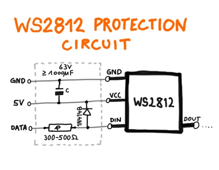
display.temperature(23)I use this circuit when I connect WS2812 "neo pixels" to micro controllers (connected to DATA pin).
(c) Copyright 2018-2021 by Jan Delgado. License: MIT

