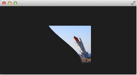
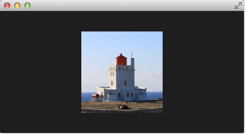
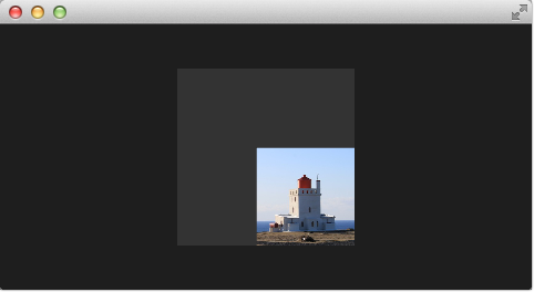
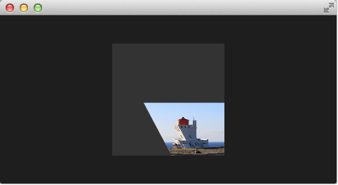
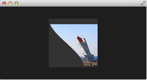
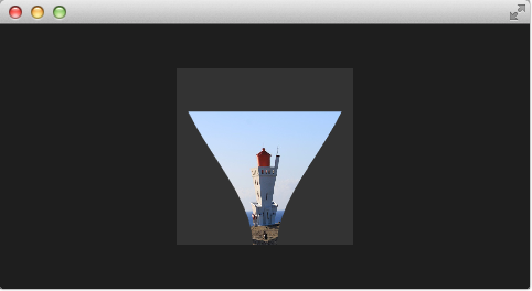
The vertex shader can be used to manipulate the vertexes provided by the shader effect. In normal cases, the shader effect has 4 vertexes (top-left, top-right, bottom-left and bottom-right). Each vertex reported is from type vec4. To visualize the vertex shader we will program a genie effect. This effect is used to let a rectangular window area vanish into one point, like a genie disappearing into a lamp.
First, we will set up our scene with an image and a shader effect.
<<< @/docs/ch10-effects/src/effects/genie/0/genie0.qml#M1
This provides a scene with a dark background and a shader effect using an image as the source texture. The original image is not visible on the image produced by our genie effect. Additional we added a dark rectangle on the same geometry as the shader effect so we can better detect where we need to click to revert the effect.
The effect is triggered by clicking on the image, this is defined by the mouse area covering the effect. In the onClicked handler we toggle the custom boolean property minimized. We will use this property later to toggle the effect.
After we have set up the scene, we define a property of type real called minimize, the property will contain the current value of our minimization. The value will vary from 0.0 to 1.0 and is controlled by a sequential animation.
<<< @/docs/ch10-effects/src/effects/genie/1/genie1.qml#M1
The animation is triggered by the toggling of the minimized property. Now that we have set up all our surroundings we finally can look at our vertex shader.
<<< @/docs/ch10-effects/src/effects/genie/1/genie1.vert#M1
The vertex shader is called for each vertex so four times, in our case. The default qt defined parameters are provided, like qt_Matrix, qt_Vertex, qt_MultiTexCoord0, qt_TexCoord0. We have discussed the variable already earlier. Additional we link the minimize, width and height variables from our shader effect into our vertex shader code. In the main function, we store the current texture coordinate in our qt_TexCoord0 to make it available to the fragment shader. Now we copy the current position and modify the x and y position of the vertex:
vec4 pos = qt_Vertex;
pos.y = mix(qt_Vertex.y, ubuf.height, ubuf.minimize);
pos.x = mix(qt_Vertex.x, ubuf.width, ubuf.minimize);
The mix(…) function provides a linear interpolation between the first 2 parameters on the point (0.0-1.0) provided by the 3rd parameter. So in our case, we interpolate for y between the current y position and the height based on the current minimized value, similar for x. Bear in mind the minimized value is animated by our sequential animation and travels from 0.0 to 1.0 (or vice versa).
The resulting effect is not really the genie effect but is already a great step towards it.
So minimized the x and y components of our vertexes. Now we would like to slightly modify the x manipulation and make it depending on the current y value. The needed changes are pretty small. The y-position is calculated as before. The interpolation of the x-position depends now on the vertexes y-position:
float t = pos.y / ubuf.height;
pos.x = mix(qt_Vertex.x, ubuf.width, t * minimize);
This results in an x-position tending towards the width when the y-position is larger. In other words, the upper 2 vertexes are not affected at all as they have a y-position of 0 and the lower two vertexes x-positions both bend towards the width, so they bend towards the same x-position.
As the bending is not really satisfying currently we will add several parts to improve the situation. First, we enhance our animation to support an own bending property. This is necessary as the bending should happen immediately and the y-minimization should be delayed shortly. Both animations have in the sum the same duration (300+700+1000 and 700+1300).
We first add and animate bend from QML.
<<< @/docs/ch10-effects/src/effects/genie/3/genie3.qml#M1
We then add bend to the uniform buffer, ubuf and use it in the shader to achieve a smoother bending.
<<< @/docs/ch10-effects/src/effects/genie/3/genie3.vert#M1
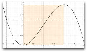
The curve starts smooth at the 0.0 value, grows then and stops smoothly towards the 1.0 value. Here is a plot of the function in the specified range. For us, only the range from 0..1 is from interest.
We also need to increase the number of vertex points. The vertex points used can be increased by using a mesh.
mesh: GridMesh { resolution: Qt.size(16, 16) }The shader effect now has an equality distributed grid of 16x16 vertexes instead of the 2x2 vertexes used before. This makes the interpolation between the vertexes look much smoother.
You can see also the influence of the curve being used, as the bending smoothes at the end nicely. This is where the bending has the strongest effect.
As a final enhancement, we want to be able to switch sides. The side is towards which point the genie effect vanishes. Until now it vanishes always towards the width. By adding a side property we are able to modify the point between 0 and width.
ShaderEffect {
    ...
    property real side: 0.5
    ...
}
<<< @/docs/ch10-effects/src/effects/genie/4/genie4.vert#M1
The last thing to-do is packaging our effect nicely. For this, we extract our genie effect code into an own component called GenieEffect. It has the shader effect as the root element. We removed the mouse area as this should not be inside the component as the triggering of the effect can be toggled by the minimized property.
<<< @/docs/ch10-effects/src/effects/genie/demo/GenieEffect.qml#M1 <<< @/docs/ch10-effects/src/effects/genie/demo/genieeffect.vert#M1
You can use now the effect simply like this:
<<< @/docs/ch10-effects/src/effects/genie/demo/geniedemo.qml#M1
We have simplified the code by removing our background rectangle and we assigned the image directly to the effect, instead of loading it inside a standalone image element.
