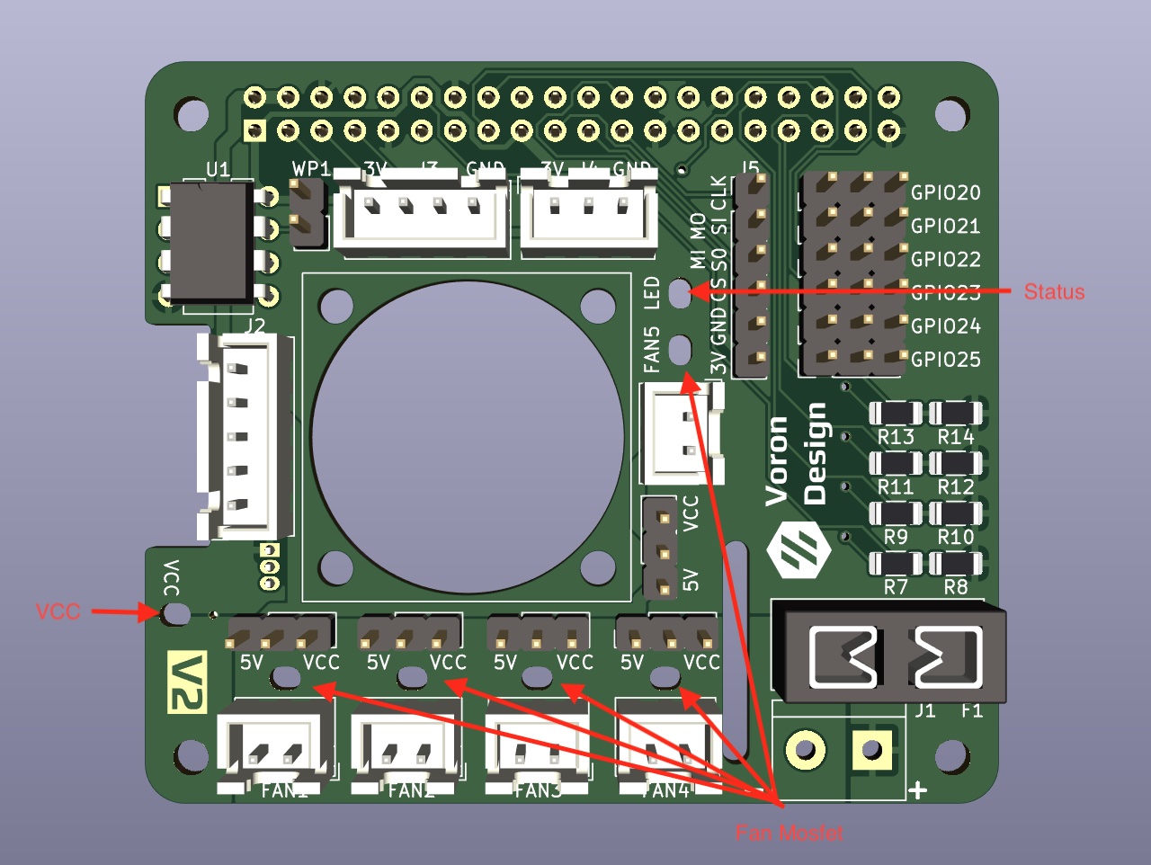
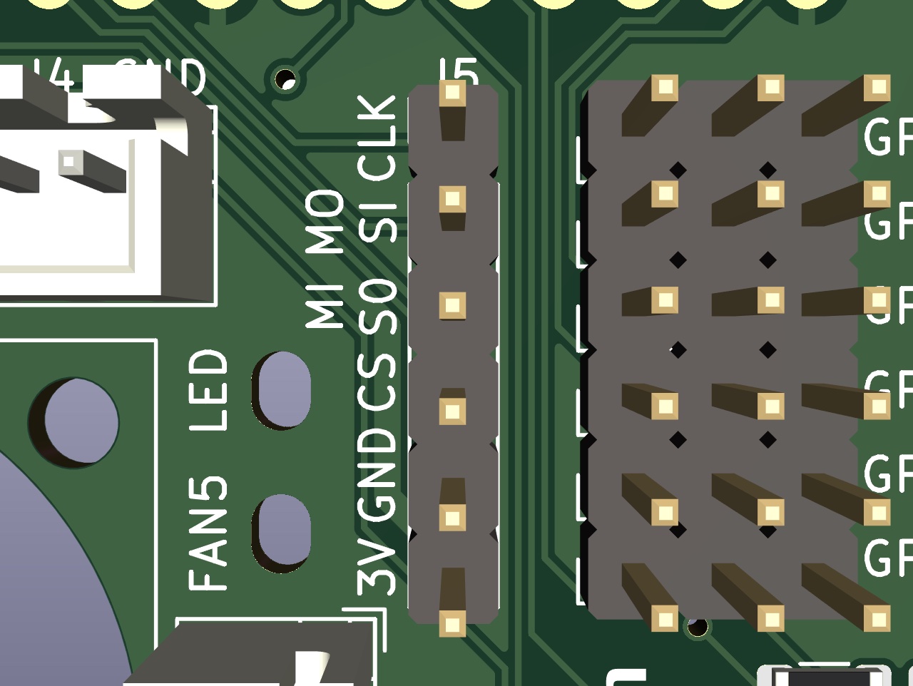
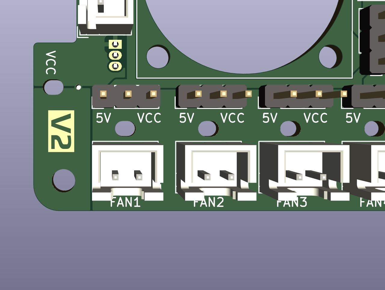
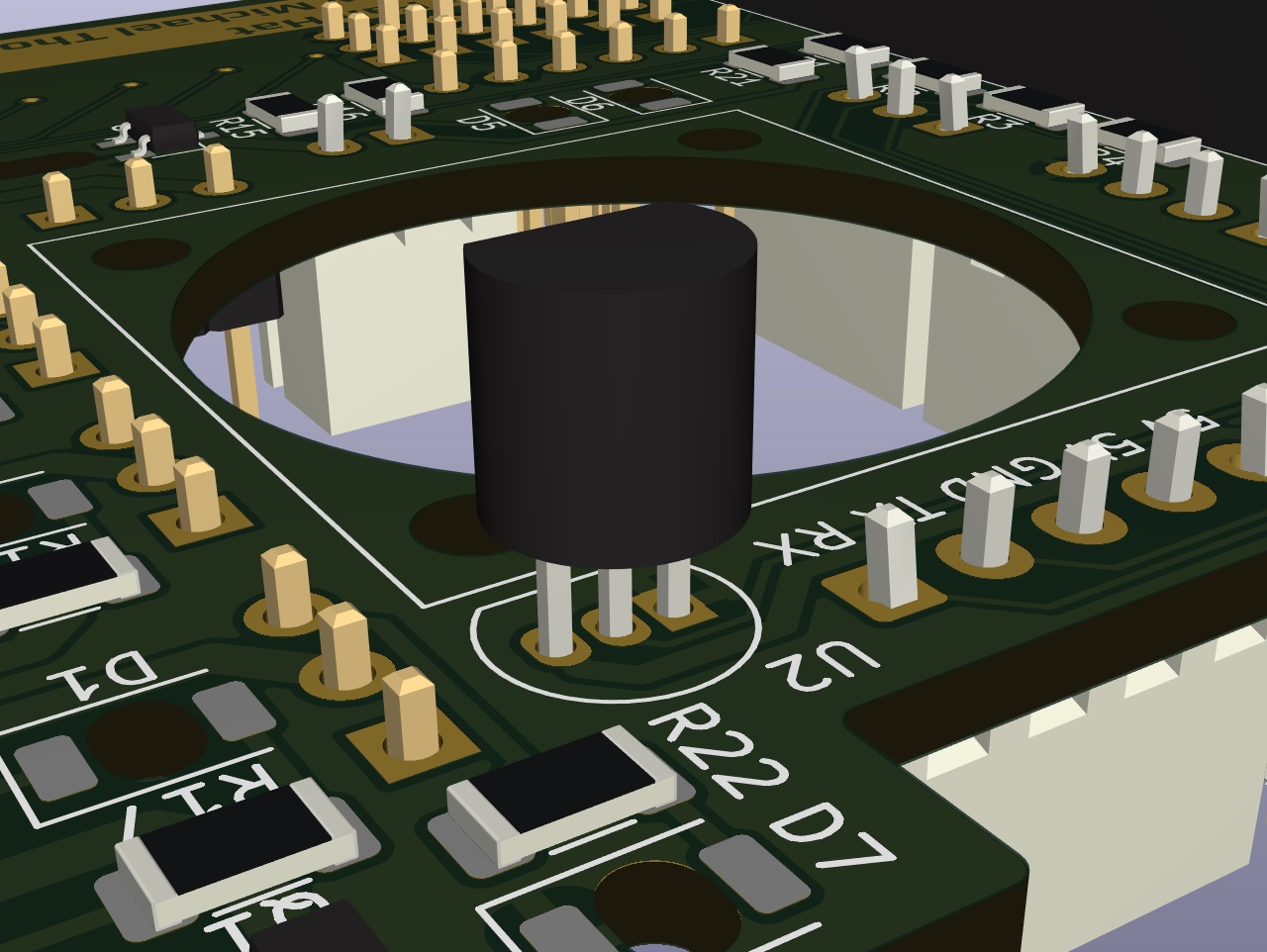
There are 7 status indicator LEDs on the board:
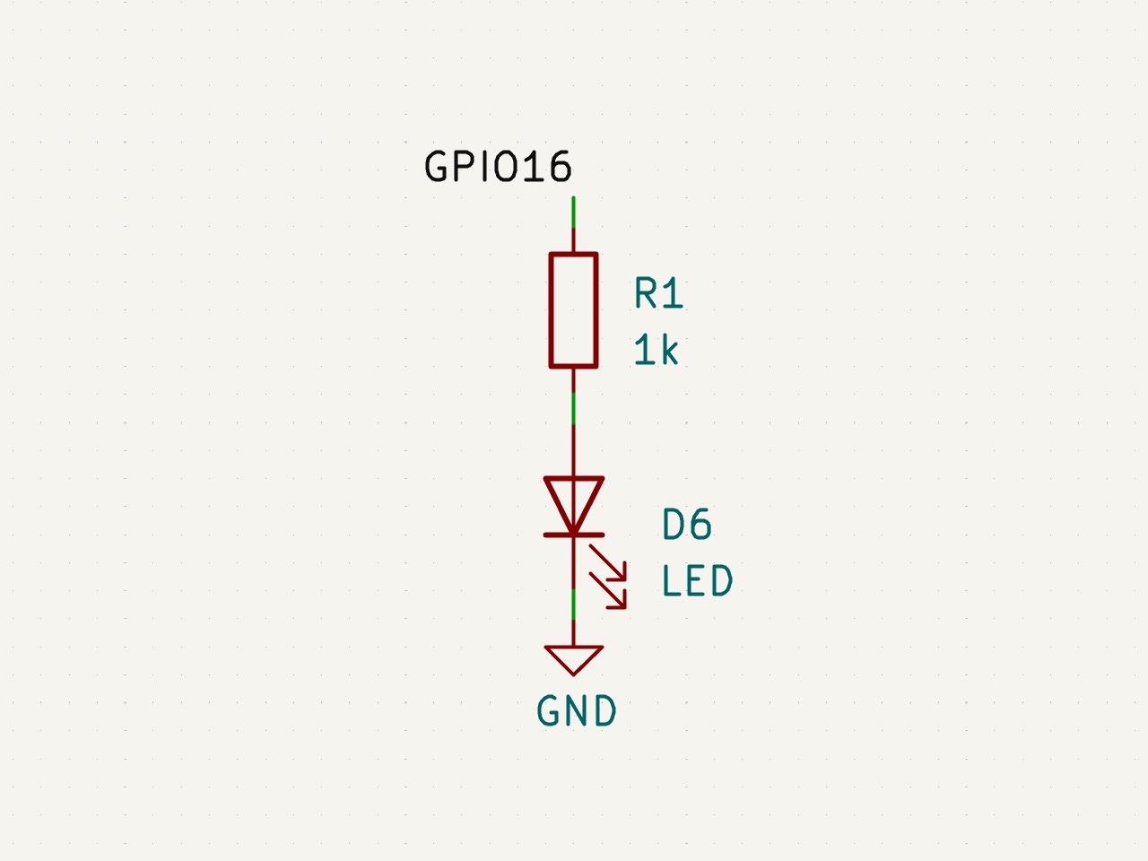
- Status LED to indicate that the board is communicating with Klipper (LED)
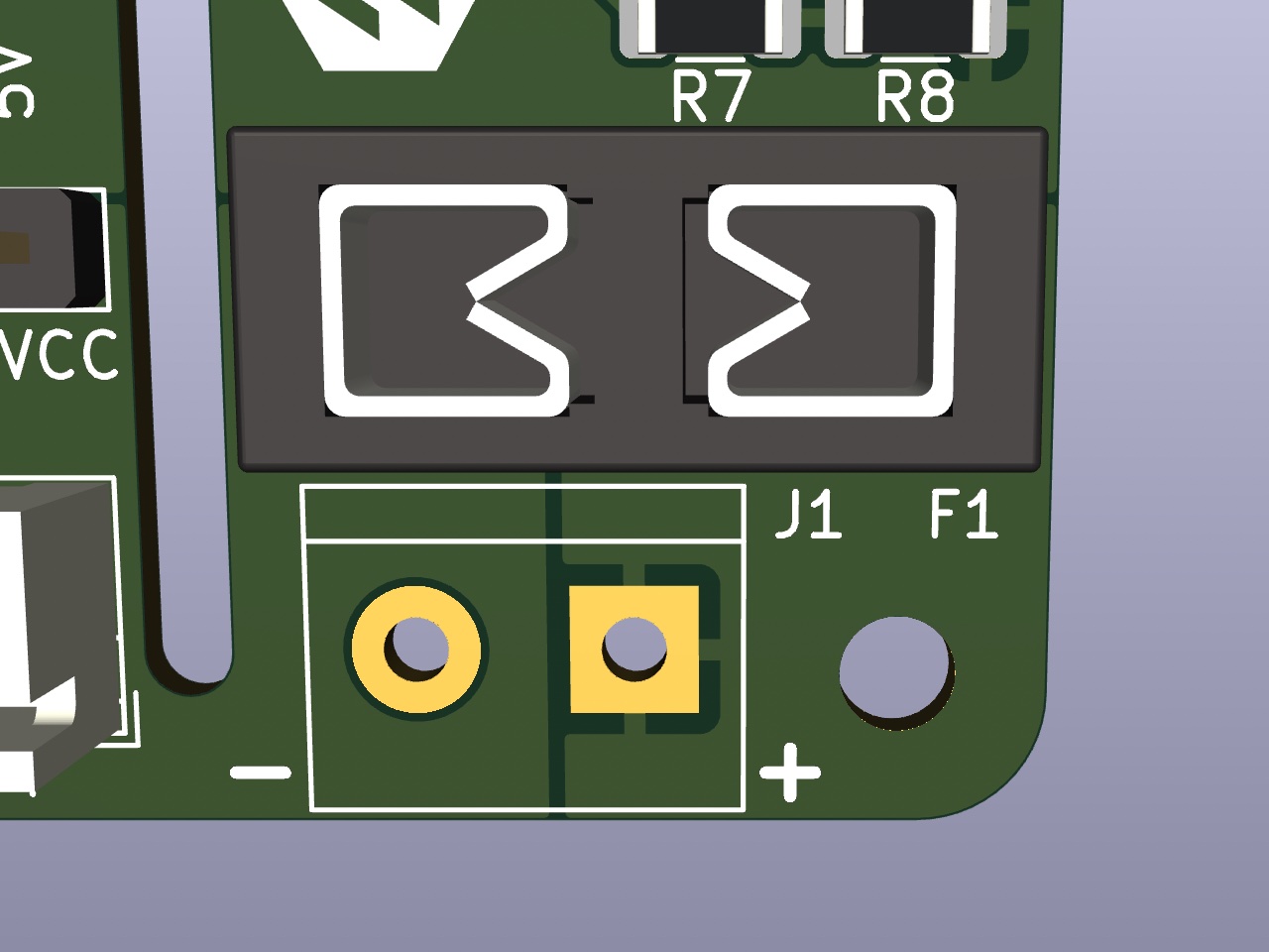
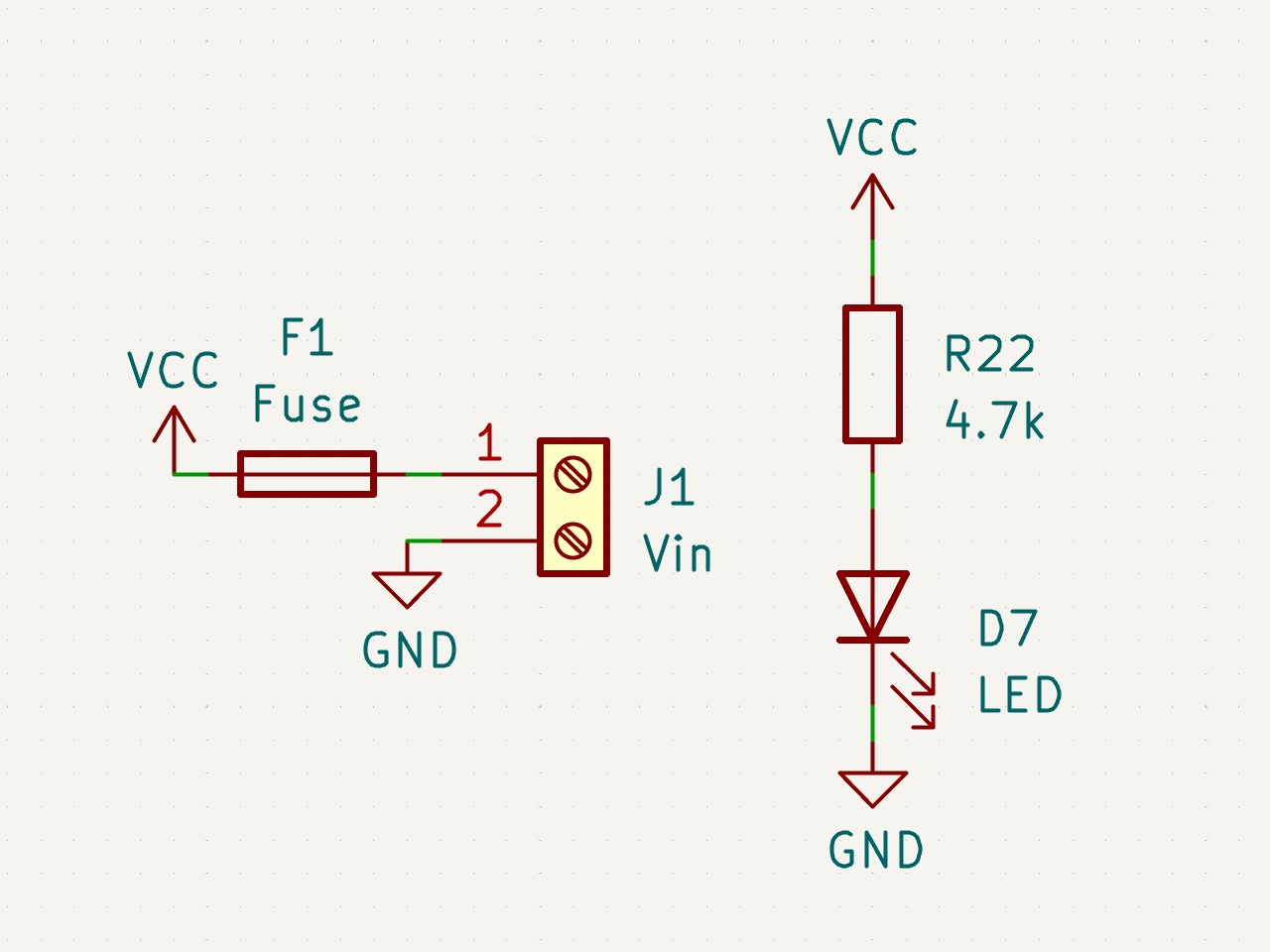
- VCC status indicates that there is power present on the Vin and GND feeding the board through the screw terminals (J1)
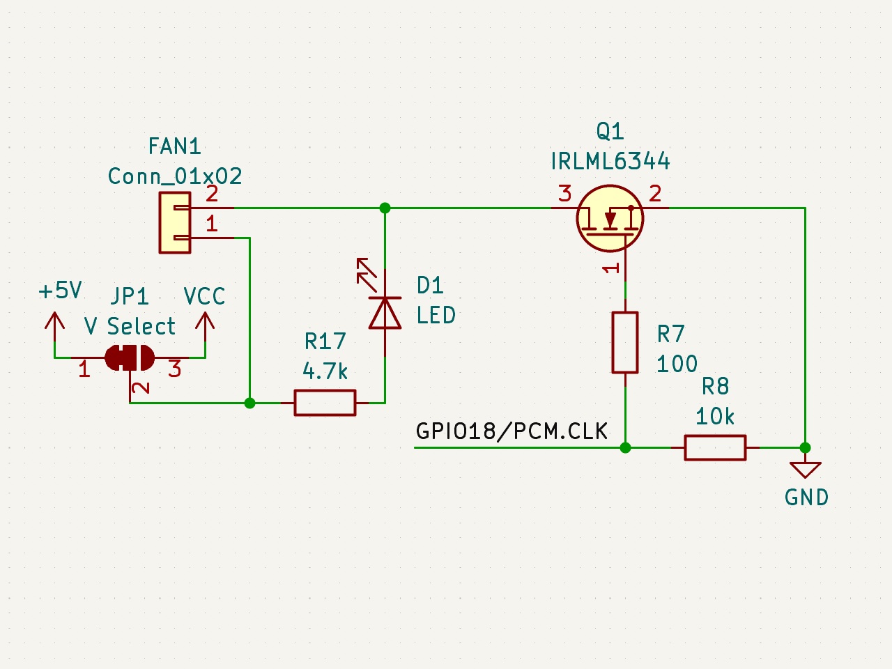
- 5 Fan Status LEDs to indicate if the Fan Mosfets have power applied to them (FAN1-FAN5)
The Status LED is connected directly to GPIO16 with a current limiting resistor.
Example klipper ready status configuration:
[static_digital_output status_led]
pins: rpi:gpio16VCC and GND are for feeding power to the Mosfets, this would typically be either 12V or 24V.
The fuse is a micro blade type fuse and should be chosen to the maximum draw of all of the MOSFET fed devices.
For example, if you are running a 40W heater, 2 5W fans and 1 2W fan, you will need a total of 62W of power. At 24V, this would translate to 62W/24V = 2.58A. The closest fuse might be a 5A fuse, which you should use.
Maximum power should not exceed 12A as the MOSFETs are each rated to a maximum of 3A.
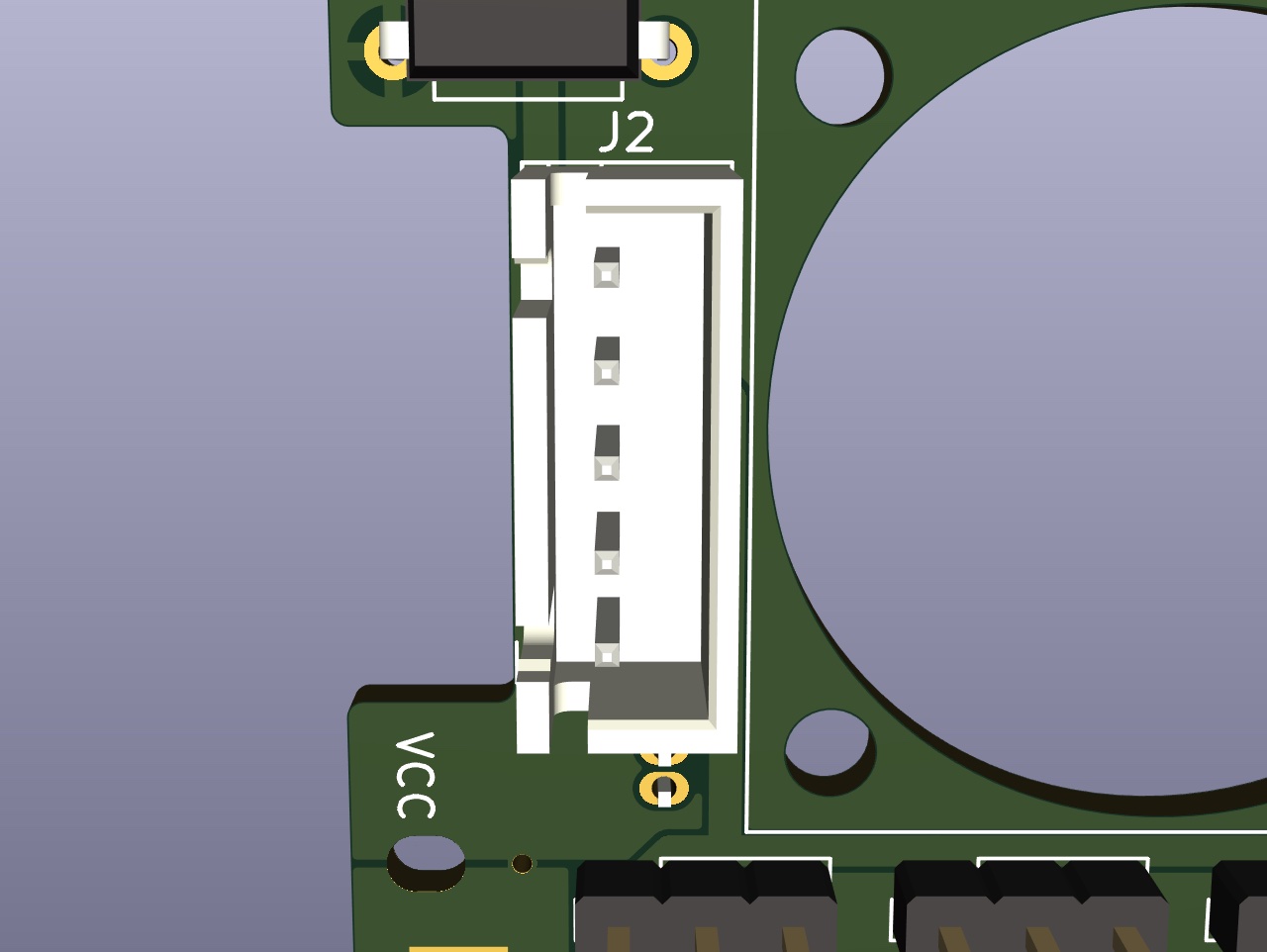
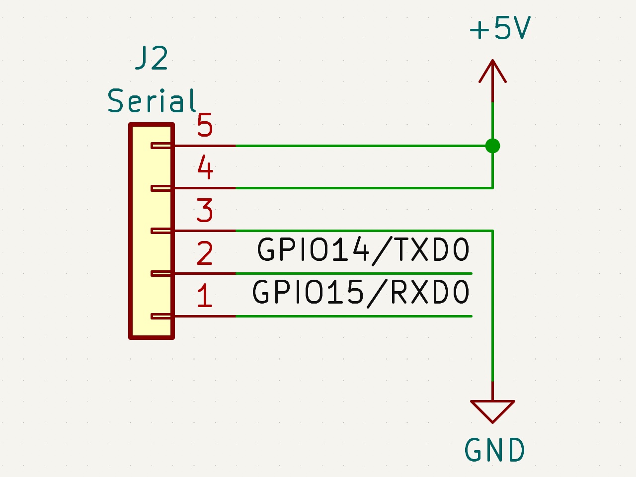
SKR Pico compatible interface, can be used to both power the Raspberry Pi and communicate with the MCU over Serial.
The 5V pins are connected directly to the Raspberry Pi 5V pins and also supply 5V to the mosfet power selector headers.
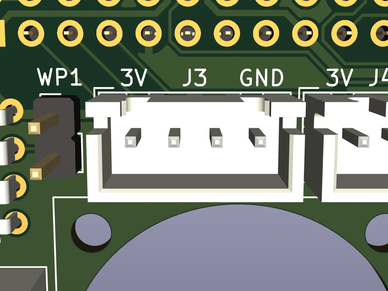
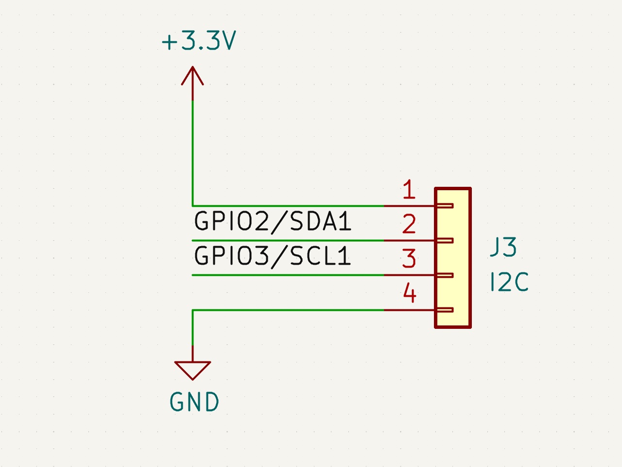
Contains a 3.3V I2C bus for connecting displays, and other sensors such as environemntal sensors and breakout expanders. This plugs into J3.
There are no Pull Up resistors on the I2C Bus as the Raspberry Pi already includes them.
Example display configuration:
[display]
lcd_type: sh1106
i2c_mcu: rpi
i2c_bus: i2c.1
Example HTU21D temperature sensor configuration:
[temperature_sensor enclosure_temp]
sensor_type: HTU21D
i2c_mcu: rpi
i2c_bus: i2c.1

[gcode_macro QUERY_ENCLOSURE]
gcode:
    {% set sensor = printer["htu21d enclosure_temp"] %}
    {action_respond_info(
        "Temperature: %.2f C\n"
        "Humidity: %.2f%%" % (
            sensor.temperature,
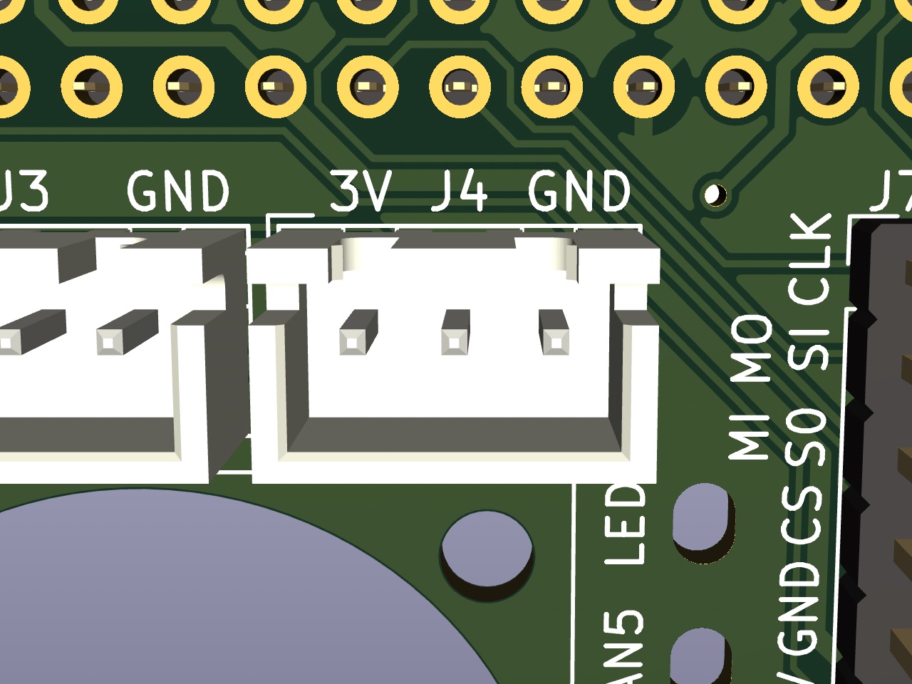
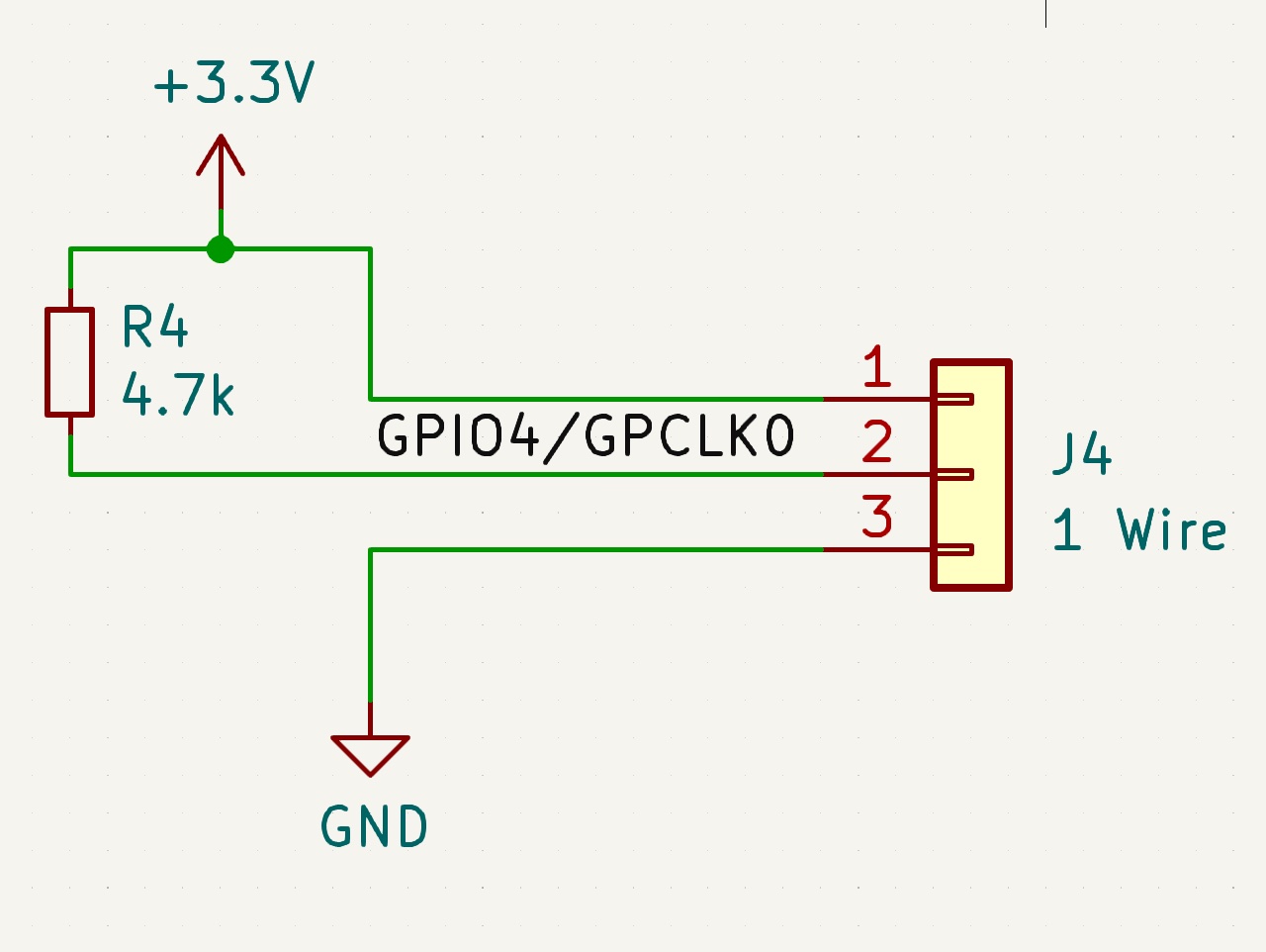
sensor.humidity))}The 1-wire connector can be used for connecting 1-wire sensors or can also be used as another generic GPIO Header.
The 1-wire pin, GPIO4 is pulled up to 3V3 with a 4.7k resistor.
Example Output Pin configuration:
[output_pin gpio4]
pin: rpi:gpio4
value: 0
shutdown_value: 0
Example DS18B20 temperature sensor configuration:
[temperature_sensor enclosure_temp]
sensor_type: DS18B20
serial_no: 28-031674b175ff # Find with: ls /sys/bus/w1/devices/
ds18_report_time: 3.0 # Seconds between readings, minimum of 1.0
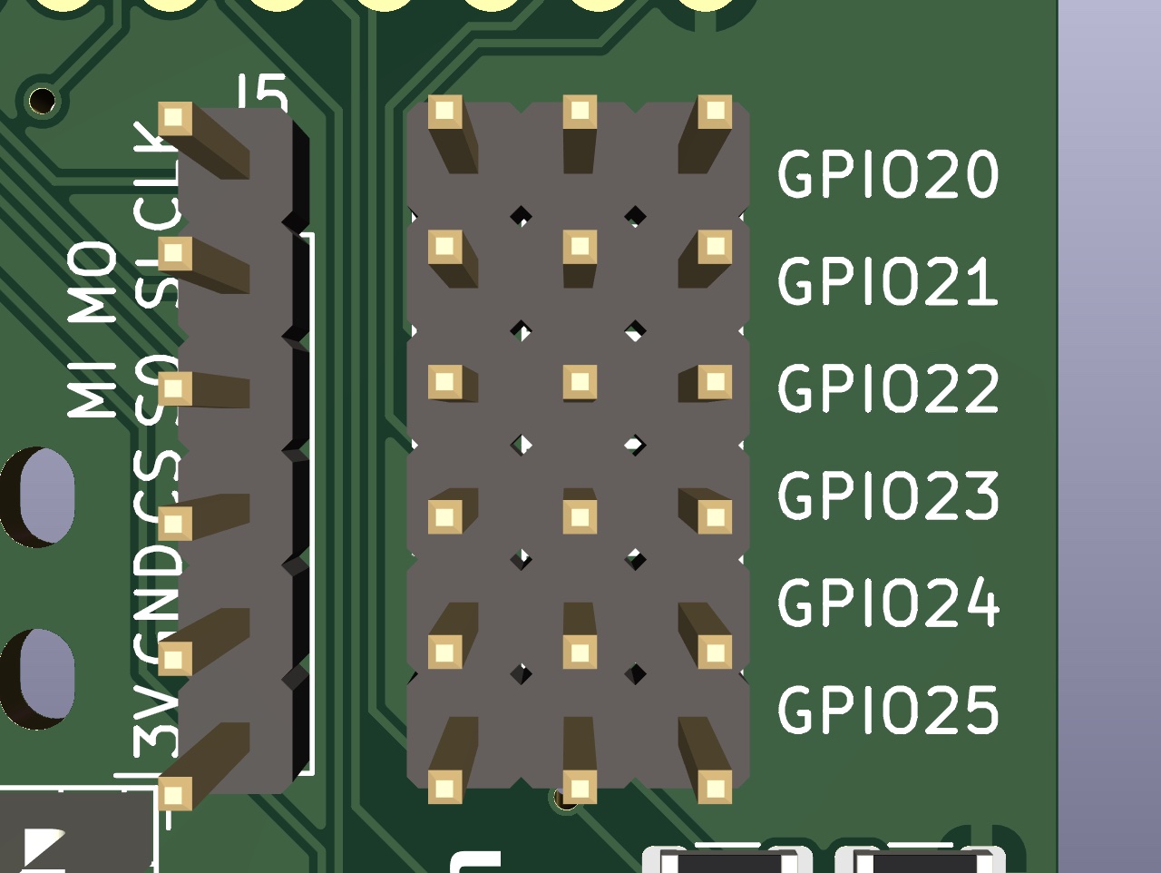
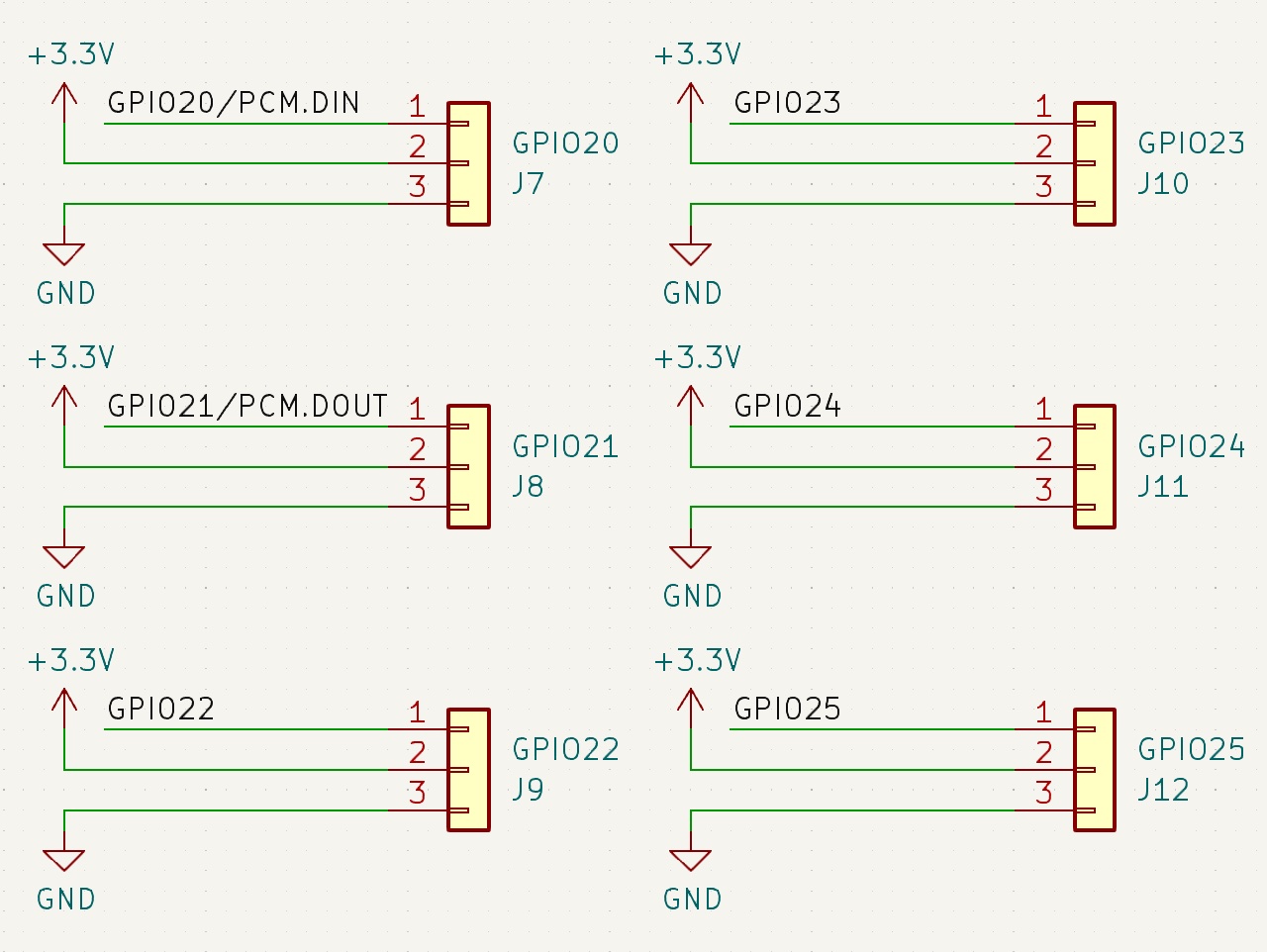
sensor_mcu: rpiThe GPIO headers GPIO20 - GPIO25 (GPIO, 3V3, GND) is available for creative uses.
Examples of what this can be used for include adding external mosfets, relays or a filament runout sensors.
Example Output Pin configuration:
[output_pin gpio20]
pin: rpi:gpio20
value: 0
shutdown_value: 0
Example Filament Sensor configuration:
[filament_switch_sensor filament_sensor]
pause_on_runout: true
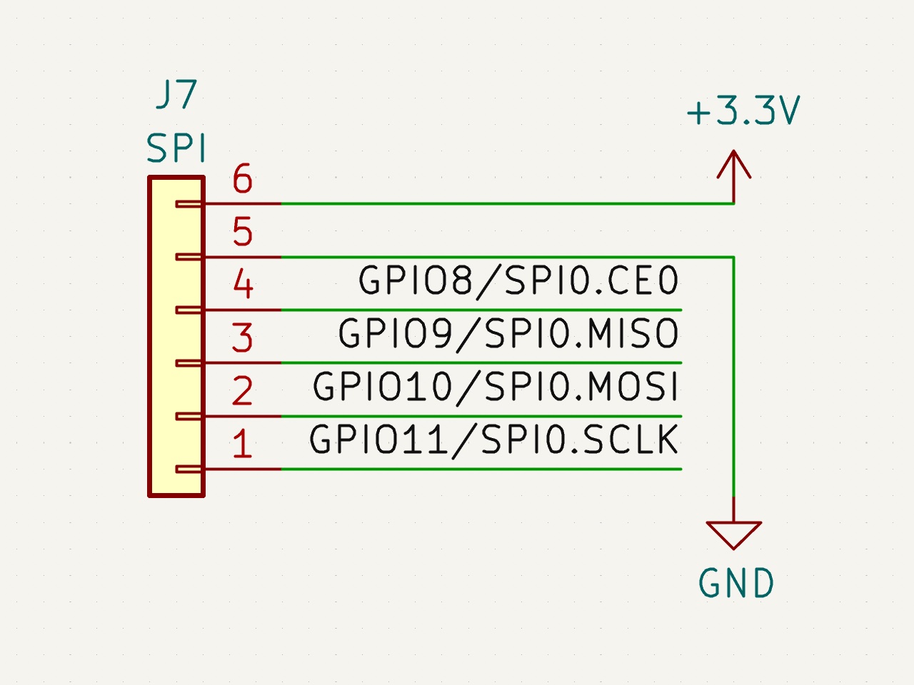
switch_pin: ^!rpi:gpio20Contains a 3.3V SPI bus for connecting displays, and other sensors such as environmental sensors and breakout expanders. This plugs into J7.
This connects directly to the Raspberry Pi's SPI0 and uses CE0, CE1 is left unconnected.
Example AXDL345 configuration:
[adxl345]
cs_pin: rpi:None

[resonance_tester]
accel_chip: adxl345
probe_points: 150, 150, 205 x 3A mosfets for controlling LED's, Heater, Fans, and other accessories connected to pins GPIO12, GPIO13, GPIO17, GPIO18 and GPIO19.
The voltage selector header can be used to connect each mosfet to either the 5V rail or VCC.
Example Output Pin configuration:
[output_pin mosfet1]
pin: rpi:gpio18
value: 0
shutdown_value: 0
Example Fan configuration:
[fan_generic fan1]
pin: rpi:gpio18
Example Hardware PWM Fan configuration:
[fan_generic fan1]
pin: rpi:pwmchip0/pwm0
hardware_pwm: trueAn example config to set up the Temperature sensor is available in the 1-wire Header section.
If you purchased your board already assembled, it is likely that the hat EEPROM has already been flashed. However, if you are building it yourself you will need Flash the EEPROM by following this guide.
You should just be able to go through the Klipper RPi micro-controller setup guide, and that page will be the most up-to-date with the latest Klipper version.
If you want to use the host as a secondary MCU the klipper_mcu process must run before the klippy process.
After installing Klipper, install the script. run:
cd ~/klipper/
sudo cp ./scripts/klipper-mcu.service /etc/systemd/system/
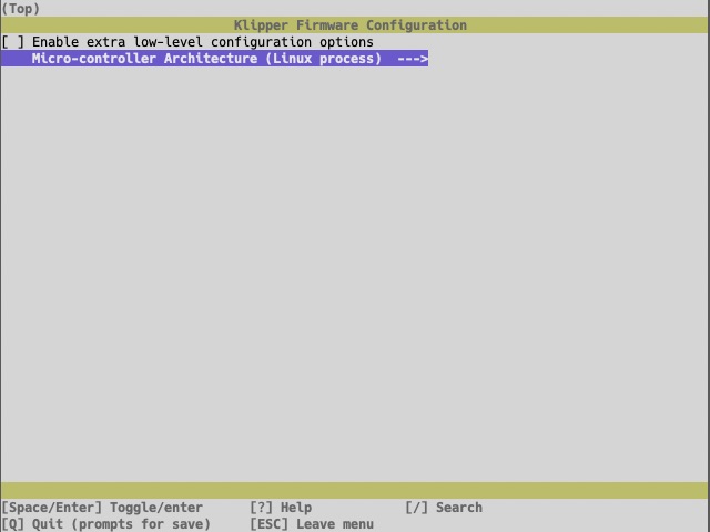
sudo systemctl enable klipper-mcu.serviceTo compile the Klipper micro-controller code, start by configuring it for the Linux process:
cd ~/klipper/
make menuconfig
In the menu, set Micro-controller Architecture to Linux process, then save and exit.
To build and install the new micro-controller code, run:
sudo service klipper stop
make flash
sudo service klipper start
If klippy.log reports a Permission denied error when attempting to connect to /tmp/klipper_host_mcu then you need to add your user to the tty group. The following command will add the pi user to the tty group:
sudo usermod -a -G tty piYou can copy the config from the EEPROM chip of the hat into the Klipper config directory:
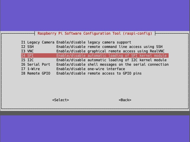
cat /proc/device-tree/hat/custom_1 > ~/printer_data/config/klipper-fan-hat.cfgSPI should be enabled automatically by the hat EEPROM, If you have trouble, you can enable it manually by running sudo raspi-config and enabling SPI under the Interfacing options menu.
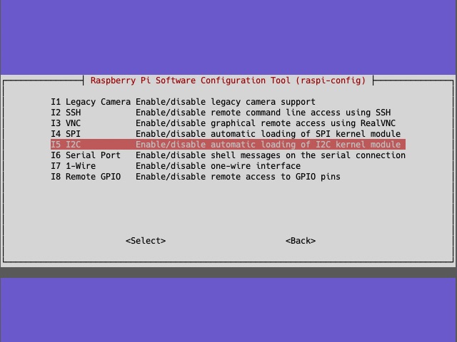
I2C should be enabled automatically by the hat EEPROM, If you have trouble, you can enable it manually by running sudo raspi-config and enabling I2C under the Interfacing options menu.
If planning to use I2C for the MPU accelerometer, it is also required to set the baud rate to 400000 by: adding/uncommenting dtparam=i2c_arm=on,i2c_arm_baudrate=400000 in /boot/config.txt (or /boot/firmware/config.txt in some distros).
This should also be automatically be enabled by the hat EEPROM however you can do it manually if you have any problems.
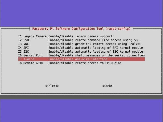
If you require, you can enable the 1-wire interface by running sudo raspi-config and enabling 1-wire under the Interfacing options menu.
you can then find any conneted sensors serial numbers with: ls /sys/bus/w1/devices/
Raspberry Pi's have two PWM channels (PWM0 and PWM1) which are exposed on the header or if not, can be routed to existing gpio pins. The Linux mcu daemon uses the pwmchip sysfs interface to control hardware pwm devices on Linux hosts. The pwm sysfs interface is not exposed by default on a Raspberry and can be activated by adding a line to /boot/config.txt:
# Enable pwmchip sysfs interface
dtoverlay=pwm,pin=12,func=4
This example enables only PWM0 and routes it to gpio12. If both PWM channels need to be enabled you can use pwm-2chan:
# Enable pwmchip sysfs interface
dtoverlay=pwm-2chan,pin=12,pin2=13,func=4,func2=4
The overlay does not expose the pwm line on sysfs on boot and needs to be exported by echo'ing the number of the pwm channel to /sys/class/pwm/pwmchip0/export:
echo 0 > /sys/class/pwm/pwmchip0/exportIf you have enabled pwm-2chan you can enable PWM1 too with:
echo 1 > /sys/class/pwm/pwmchip0/exportThis will create device /sys/class/pwm/pwmchip0/pwm0 and optionally /sys/class/pwm/pwmchip0/pwm1 in the filesystem. The easiest way to do this is by adding them to /etc/rc.local before the exit 0 line.
With the sysfs in place, you can now use either the pwm channel(s) by adding the following piece of configuration to your klipper-fan-hat.cfg:
[fan_generic fan1]
pin: rpi:pwmchip0/pwm0
hardware_pwm: true
cycle_time: 0.000001
This will add hardware pwm control to gpio12 on the Pi (because the overlay was configured to route pwm0 to pin=12).
PWM0 can be routed to gpio12 and gpio18, PWM1 can be routed to gpio13 and gpio19:
| PWM | gpio PIN | Func |
|---|---|---|
| 0 | 12 | 4 |
| 0 | 18 | 2 |
| 1 | 13 | 4 |
| 1 | 19 | 2 |
