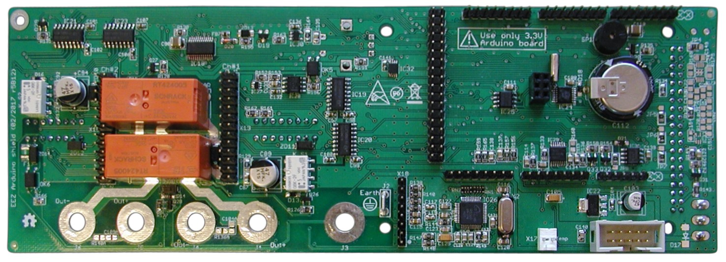
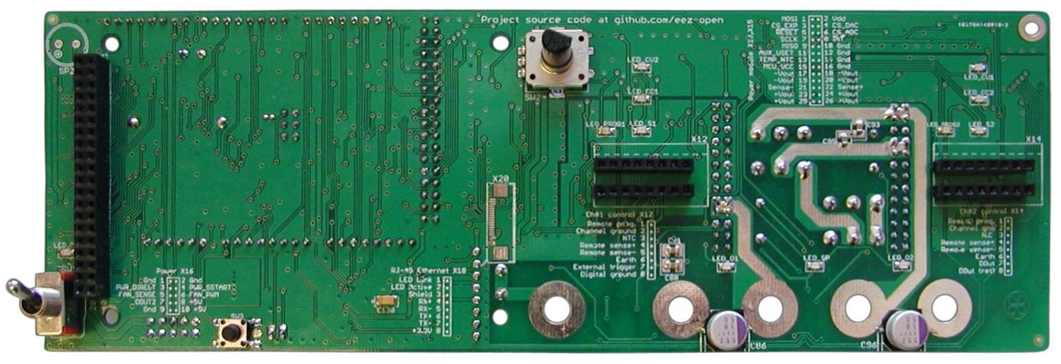
Please refer to the BOM in Consolidated/BOM folder where Board Name (Col F) is Arduino shield. Eagle files is available in Consolidated/Eagle files folder.


Revision history:
- 2017-02-23: r5B12
- 2017-01-11: r4B2
- 2016-12-11: r4B1
- 2016-10-24: r3B5
- 2016-07-23: r3B4 (Version 2.0 on github)
- Corrected WATCHDOG functionality, added possibility to choose between RESET and Power off if MCU stalled
- Optimized number of parts size and values, renumbered reference designators
- 2016-06-14: r3B3
- Removed suport for Mega2560 - only 3.3 V board such as Due (and hopefully soon STAR - OTTO is supported
- TFT touch screen rotated (landscape view) for housing in more compact (2U height) enclosure. Tested with both SSD1289 and ILI9341 display controllers
- Reset supervisor and watchdog (TPS3705-33)
- Power connector replaced with 10-pin IDC to carry master sync out
- W5500 Ethernet controller
- 10-pin IDC for channel's SPI bus replaced with 26-pin IDC that carry output power signals, remote sense, remote programming, temperature sensor and SMPS sync
- Redesigned wiring of output serial/parallel connection
- Ethernet RJ-45 connector replaced with 8-pin 0.1" header (see also new AUX PS board)
- 2x5-pin 0.1" header for optional W5500 Ethernet module (eBay)
- 2x4-pin 0.1" header for optional NRF24L01 Wifi module (eBay)
- Added support for incremental encoder
- 4 mm binding posts for remote sensing inputs replaced with 0.1" push-in connector
- New numbering in sync with consolidated schematics
- 2016-04-06: r1B14 (Version 1.0 on github)
- Added fan control (FAN_PWM, FAN_SENSE)
- Power connector replaced with 6-pin IDC as on the AUX PS r4B41
- Removed optional reset connector
- 2016-03-28: r1B13a
- Change remote sense inputs position on X4
- 2016-03-27: r1B13
- Fixed remote sense wiring
- Output protection redesigned (TVS moved, SAR and MOVs removed)
- Smaller footprint
- Remote sense 4 mm banana binding posts replaced with compact "push-in" connectors
- Digital trigger input (with buffer and level shifter) added
- THT LEDs replaced with SMD counterparts (lightpipes are now required)
- 2015-12-07: r1B12b - First public release
This product is made available under the terms of the TAPR Open Hardware License. See the LICENSE.TXT file that accompanies this distribution for the full text of the license.
Repository: www.github.com/eez-open
Web site: www.envox.hr/eez
Consult EEZ PSU Arduino pin mapping r5B12.odt for Arduino pins assignements and EEZ PSU Arduino shield+BP TLC5925 codes r3B3.odt for binding posts connections and LED indications.