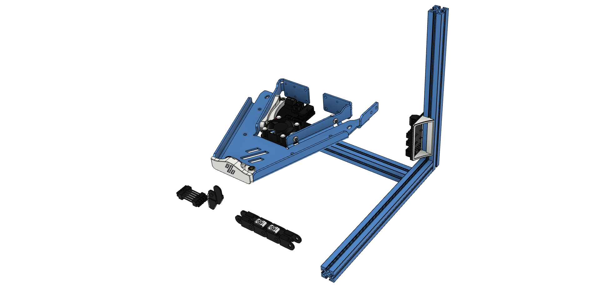
This mod adds two PCBs (Frame PCB, Kirigami PCB) and a cable (Cable) to the V0.1/V0.2 that can aid in wire management and routing.
There are also optional things like a Bed Fan or a Kirigami-Front.
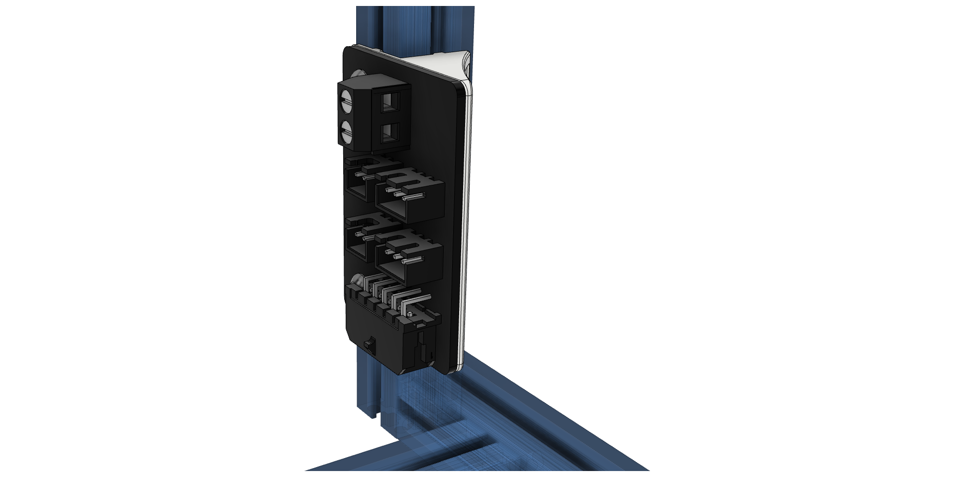
The frame PCB mounts on the side in the electronics bay of the printer and combines all cables into a single 10 pin Micro-Fit 3.0 connector. (With neopixel loop-through.)
| Part | Quantity V1/V2 | Notes | LCSC Part Number | Link |
|---|---|---|---|---|
| 10 Pin Socket (Right Angle) | 1 | MOLEX 430451000 | C122421 | lcsc |
| 2 pin JST XH | 2 | 2.5mm pitch | C158012 | lcsc |
| 3 pin JST XH | 2 | 2.5mm pitch | C144394 | lcsc |
| Screw Terminal | 1 | 5.08mm pitch | digikey | |
| Screw M3x8 | 2 | |||
| Nut M3 | 2 |
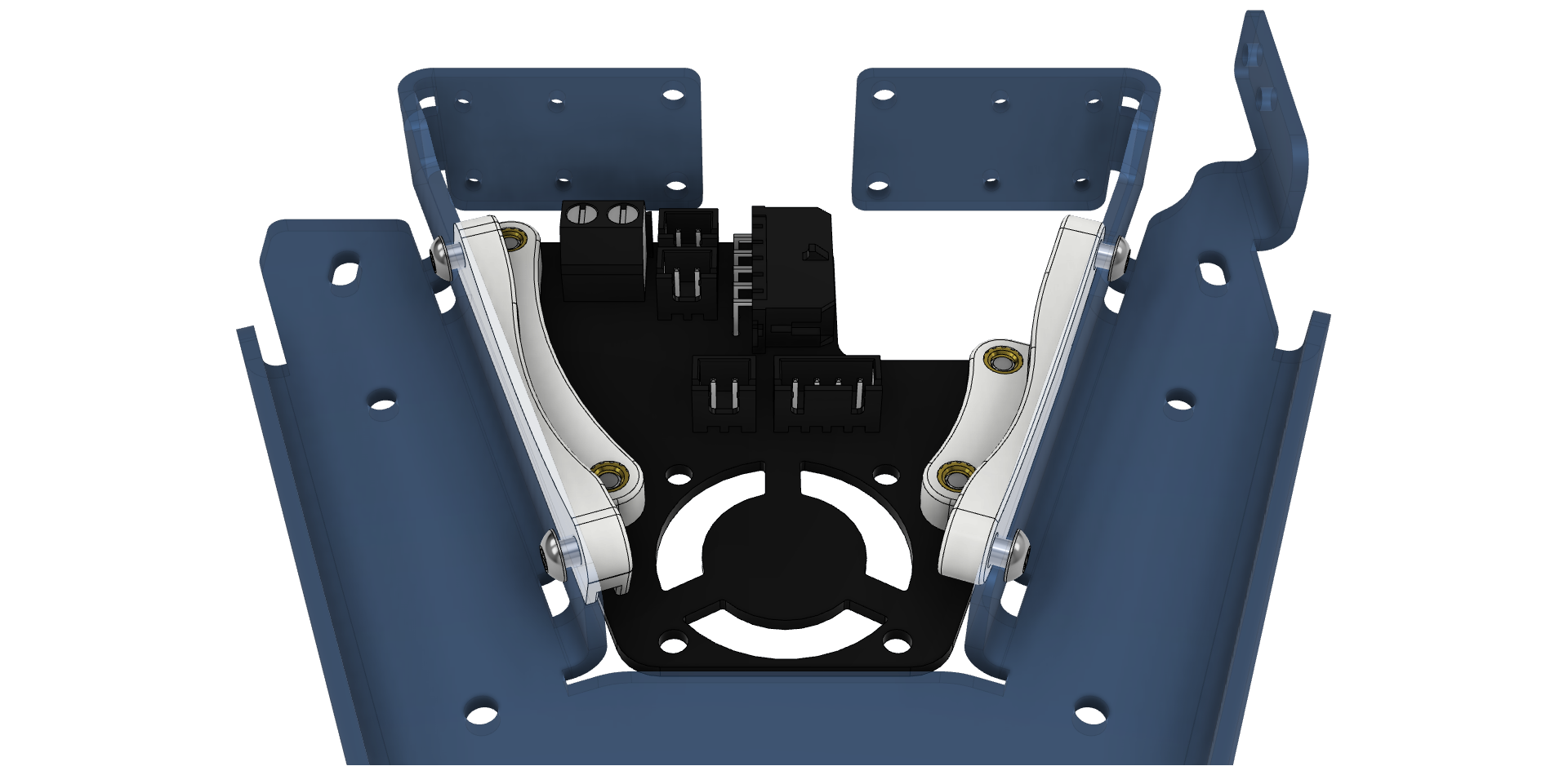
Mounted on the Kirigami bed mount, this breaks out the 10 pin harness into all needed connectors.
| Part | Quantity V1 | Quantity V2 | Notes | LCSC Part Number | Link |
|---|---|---|---|---|---|
| 10 Pin Socket (Right Angle) | 1 | 1 | MOLEX 430451000 | C122421 | lcsc |
| 2 pin JST XH | 4 | 3 | B2B-XH | C158012 | lcsc |
| 4 pin JST XH | 1 | 1 | B4B-XH | C144395 | lcsc |
| Screw Terminal | 1 | 5.08mm pitch | digikey | ||
| Screw M3x6 | 8 | 8 | (Or M3x8) | ||
| Heat-Set Inserts | 8 | 8 | Voron-spec |
| Part | Quantity | Notes | LCSC Part Number | Link |
|---|---|---|---|---|
| 0805 10uF Capacitor | 1 | Use if using BARE neopixel IC's. | C162422 | lcsc |
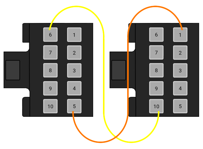
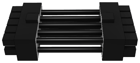
The Cable is a dual ended 10P (2x5) microfit cable. The connectors are wired 1:5, 6:10 so pin 1 connects to pin 5, pin 2 connects to pin 4 and so forth for all 10 pins.
Only 2 of the 10 wires are shown for clarity. Connect each number to its opposite. (in it's row!)
Symbolic representation of the connection:
| Part | Quantity | Notes | LCSC Part Number | Link |
|---|---|---|---|---|
| 10 Pin Plug | 2 | Molex 430251400 | C259745 | lcsc |
| Microfit Crimp | 20 | Molex 430300001 | C259786 | lcsc |
| Wire | 10 | Smallest required AWG per respective function. | PTFE/Silicone/Hefulon for motion rated |
| Part | Part Number | Link |
|---|---|---|
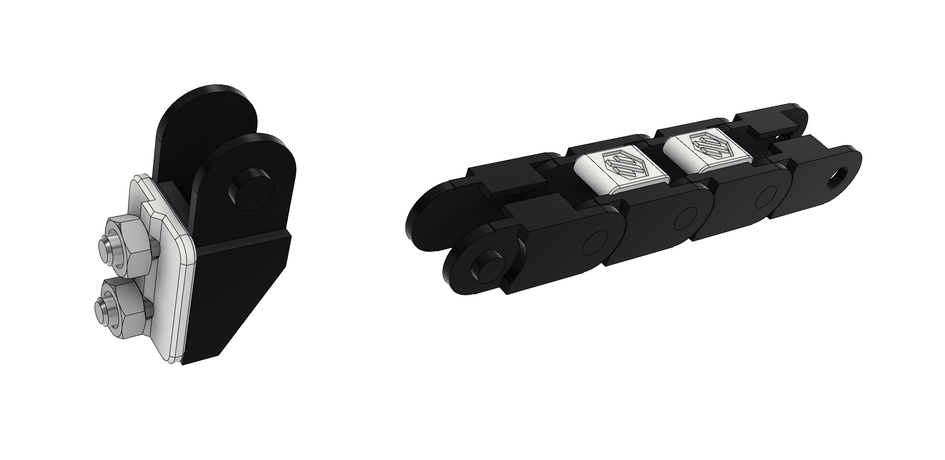
| Chain | E04.07.015.0 | igus |
| lecktor |
- Link to U.F.O. variant
- Moved Screw Terminal postition on Frame PCB and rearranged positons of the connectors + changing heater to Screw Terminal on the Kirigami PCB
- Initial Idea
