This example demonstrates how to use the inter-processor communication (IPC) driver to implement a message pipe in PSoC® 6 MCU. The pipe is used to send messages between CPUs.
See the "PSoC 6 MCU Dual-CPU Development" section in AN215656 – PSoC 6 MCU Dual-CPU System Design for instructions on how to develop dual-CPU applications.
In this example, the CM0+ CPU generates 32-bit random numbers periodically using the Crypto block. The CM4 CPU receives the random numbers from CM0+ CPU through IPC pipes. The CM4 CPU prints the random numbers to a terminal emulator. It also controls when the CM0+ CPU starts and stops creating random numbers.
-
Note: This code example version requires ModusToolbox software version 2.2 or later and is not backward compatible with v2.1 or older versions. If you can't move to ModusToolbox v2.2, please use the latest compatible version of this example: latest-v1.X.
-
Board Support Package (BSP) minimum required version: 2.0.0
-
Programming Language: C
-
Associated Parts: All PSoC 6 MCU parts with dual CPUs
- GNU Arm® Embedded Compiler v9.3.1 (GCC_ARM) - Default value of
TOOLCHAIN - Arm compiler v6.11 (ARM)
- IAR C/C++ compiler v8.42.2 (IAR)
- PSoC 6 Wi-Fi BT Prototyping Kit (CY8CPROTO-062-4343W) - Default value of
TARGET - PSoC 6 WiFi-BT Pioneer Kit (CY8CKIT-062-WIFI-BT)
- PSoC 6 BLE Pioneer Kit (CY8CKIT-062-BLE)
- PSoC 6 BLE Prototyping Kit (CY8CPROTO-063-BLE)
- PSoC 62S2 Wi-Fi BT Pioneer Kit (CY8CKIT-062S2-43012)
- PSoC 62S1 Wi-Fi BT Pioneer Kit (CYW9P62S1-43438EVB-01)
- PSoC 62S1 Wi-Fi BT Pioneer Kit (CYW9P62S1-43012EVB-01)
- PSoC 62S3 Wi-Fi BT Prototyping Kit (CY8CPROTO-062S3-4343W)
This example uses the board's default configuration. See the kit user guide to ensure that the board is configured correctly.
Note: The PSoC 6 BLE Pioneer Kit (CY8CKIT-062-BLE) and the PSoC 6 WiFi-BT Pioneer Kit (CY8CKIT-062-WIFI-BT) ship with KitProg2 installed. The ModusToolbox software requires KitProg3. Before using this code example, make sure that the board is upgraded to KitProg3. The tool and instructions are available in the Firmware Loader GitHub repository. If you do not upgrade, you will see an error like "unable to find CMSIS-DAP device" or "KitProg firmware is out of date".
Install a terminal emulator if you don't have one. Instructions in this document use Tera Term.
-
Click the New Application link in the Quick Panel (or, use File > New > ModusToolbox Application).
-
Pick a kit supported by the code example from the list shown in the Project Creator - Choose Board Support Package (BSP) dialog.
When you select a supported kit, the example is reconfigured automatically to work with the kit. To work with a different supported kit later, use the Library Manager to choose the BSP for the supported kit. You can use the Library Manager to select or update the BSP and firmware libraries used in this application. To access the Library Manager, click on the link from the Quick Panel.
You can also just start the application creation process again and select a different kit.
If you want to use the application for a kit not listed here, you may need to update the source files. If the kit does not have the required resources, the application may not work.
-
In the Project Creator - Select Application dialog, choose the example by enabling the checkbox.
-
Optionally, change the suggested New Application Name.
-
Enter the local path in the Application(s) Root Path field to indicate where the application needs to be created.
Applications that can share libraries can be placed in the same root path.
-
Click Create to complete the application creation process.
For more details, see the Eclipse IDE for ModusToolbox User Guide (locally available at {ModusToolbox install directory}/ide_{version}/docs/mt_ide_user_guide.pdf).
-
Download and unzip this repository onto your local machine, or clone the repository.
-
Open a CLI terminal and navigate to the application folder.
On Linux and macOS, you can use any terminal application. On Windows, open the modus-shell app from the Start menu.
Note: Ensure that the deps folder contains the required BSP file (TARGET_xxx.mtb) corresponding to the TARGET. Use the Library Manager (
make modlibscommand) to select and download the BSP file. If the selected kit does not have the required resources or is not supported, the application may not work. -
Import the required libraries by executing the
make getlibscommand in the cm4_app folder.
-
Follow the instructions from the CLI section to download or clone the repository, and import the libraries using the
make getlibscommand. -
Export the application to a supported IDE using the
make <ide>command. Run this command for both applications - cm0p_app and cm4_app. -
Follow the instructions displayed in the terminal to create or import the application as an IDE project.
For more details, see the "Exporting to IDEs" section of the ModusToolbox User Guide (locally available at {ModusToolbox install directory}/ide_{version}/docs/mtb_user_guide.pdf.
-
Connect the board to your PC using the provided USB cable through the USB connector.
-
Open a terminal program and select the KitProg3 COM port. Set the serial port parameters to 8N1 and 115200 baud.
-
Program the board.
-
Using Eclipse IDE for ModusToolbox:
-
Select the application project in the Project Explorer.
-
In the Quick Panel, scroll down, and click <Application Name> Program (KitProg3_MiniProg4).
-
-
Using CLI:
From the terminal, execute the
make programcommand in the cm4_app folder to build and program the application using the default toolchain to the default target. You can specify a target and toolchain manually:make program TARGET=<BSP> TOOLCHAIN=<toolchain>Example:
make program TARGET=CY8CPROTO-062-4343W TOOLCHAIN=GCC_ARM
-
-
After programming, the application starts automatically. Confirm that "IPC Pipes Example" and other text is displayed on the UART terminal.
-
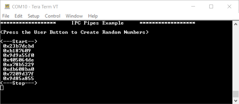
Press the user button on the kit for a few seconds. The terminal prints random numbers as shown in Figure 1. Messages are printed while the button is pressed on every second. Once the button is released, it stops.
Figure 1. Terminal Message

You can debug the example to step through the code. In the IDE, use the <Application Name> Debug (KitProg3_MiniProg4) configuration in the Quick Panel. For more details, see the "Program and Debug" section in the Eclipse IDE for ModusToolbox User Guide.
Note: (Only while debugging) On the CM4 CPU, some code in main() may execute before the debugger halts at the beginning of main(). This means that some code executes twice - before the debugger stops execution, and again after the debugger resets the program counter to the beginning of main(). See KBA231071 to learn about this and for the workaround.
In this code example, the CM4 CPU is the primary CPU, which is responsible to initialize the system. To avoid any access to uninitialized hardware, the CM0+ waits for CM4 to complete the system initialization by waiting for an IPC command. This code example handles four types of IPC commands:
IPC_CMD_INIT: CM0+ waits for this command to initialize.IPC_CMD_START: CM0+ waits for this command to enable a watchdog timer and the Crypto block.IPC_CMD_STOP: CM0+ waits for this command to disable a watchdog timer and the Crypto block.IPC_CMD_STATUS: CM4 waits for this command to print a number to the terminal.
The CM0+ CPU uses a watchdog timer to periodically wake itself up from sleep. Once it wakes up, it generates a 32-bit random number using the crypto block and sends it to the CM4 CPU.
The CM4 CPU checks if the user has pressed the kit button. When a button press is detected, CM4 informs CM0+ to start creating random numbers. When the button is released, CM4 instructs CM0+ to stop creating random numbers. When CM4 receives a message from CM0+, it parses it and prints the random number to the terminal.
Figure 2. Firmware Flowchart

This application has a different folder structure because it contains the firmware for CM4 and CM0+ applications as shown below:
|-- cm0p_app/           # CM0+ Application Folder
    |-- main.c
    |-- Makefile
    |-- deps/           # All dependencies Folder for CM0+
|-- cm4_app/            # CM4 Application Folder
    |-- main.c
    |-- Makefile
    |-- deps/           # All dependencies Folder for CM4
|-- shared/             # Shared Folder for CM0+ and CM4
    |-- include/        # Shared header files
    |-- source          # Shared source files
    |-- linker_script/  # Contains linker scripts for the ARM/GCC_ARM/IAR toolchains
When using the default BSP settings provided by the TARGET folder, it allocates only 8192 bytes of RAM and flash for the CM0+ CPU. This example requires more memory for CM0+; therefore, a custom linker script is required, which is located at shared/linker_script.
This code example uses a user pipe. The shared folder contains the implementation of a custom initialization of the system pipes, system semaphores and user pipes. Each CPU has its own initialization function. Note that the Makefile of both CPUs adds CY_IPC_DEFAULT_CFG_DISABLE=1 in the DEFINES variable. This disables the default IPC configuration that comes with the BSP.
Table 1. Application Resources
| Resource | Alias/Object | Purpose |
|---|---|---|
| GPIO (HAL) | CYBSP_USER_BTN | User button to start/stop creating random numbers |
| UART (HAL) | cy_retarget_io_uart_obj | UART HAL object used by Retarget I/O for printing to the console |
| MCWDT (PDL) | MCWDT_HW | Watchdog timer to wake up CM0+ CPU periodically |
| CRYPTO (PDL) | CRYPTO | To generate random numbers |
| Application Notes | |
|---|---|
| AN228571 – Getting Started with PSoC 6 MCU on ModusToolbox | Describes PSoC 6 MCU devices and how to build your first application with ModusToolbox |
| AN221774 – Getting Started with PSoC 6 MCU on PSoC Creator | Describes PSoC 6 MCU devices and how to build your first application with PSoC Creator |
| AN210781 – Getting Started with PSoC 6 MCU with Bluetooth Low Energy (BLE) Connectivity on PSoC Creator | Describes PSoC 6 MCU with BLE Connectivity devices and how to build your first application with PSoC Creator |
| AN215656 – PSoC 6 MCU: Dual-CPU System Design | Describes the dual-CPU architecture in PSoC 6 MCU, and shows how to build a simple dual-CPU design |
| Code Examples | |
| Using ModusToolbox | Using PSoC Creator |
| Device Documentation | |
| PSoC 6 MCU Datasheets | PSoC 6 Technical Reference Manuals |
| Development Kits | Buy at www.cypress.com |
| CY8CKIT-062-BLE PSoC 6 BLE Pioneer Kit | CY8CKIT-062-WiFi-BT PSoC 6 WiFi-BT Pioneer Kit |
| CY8CPROTO-063-BLE PSoC 6 BLE Prototyping Kit | CY8CPROTO-062-4343W PSoC 6 Wi-Fi BT Prototyping Kit |
| CY8CKIT-062S2-43012 PSoC 62S2 Wi-Fi BT Pioneer Kit | CY8CPROTO-062S3-4343W PSoC 62S3 Wi-Fi BT Prototyping Kit |
| CYW9P62S1-43438EVB-01 PSoC 62S1 Wi-Fi BT Pioneer Kit | CYW9P62S1-43012EVB-01 PSoC 62S1 Wi-Fi BT Pioneer Kit |
| Libraries | |
| PSoC 6 Peripheral Driver Library (PDL) and docs | psoc6pdl on GitHub |
| Cypress Hardware Abstraction Layer (HAL) Library and docs | psoc6hal on GitHub |
| Retarget IO - A utility library to retarget the standard input/output (STDIO) messages to a UART port | retarget-io on GitHub |
| Middleware | |
| CapSense® library and docs | capsense on GitHub |
| Links to all PSoC 6 MCU Middleware | psoc6-middleware on GitHub |
| Tools | |
| Eclipse IDE for ModusToolbox | The cross-platform, Eclipse-based IDE for IoT designers that supports application configuration and development targeting converged MCU and wireless systems. |
| PSoC Creator™ | The Cypress IDE for PSoC and FM0+ MCU development. |
Cypress provides a wealth of data at www.cypress.com to help you select the right device, and quickly and effectively integrate it into your design.
For PSoC 6 MCU devices, see How to Design with PSoC 6 MCU - KBA223067 in the Cypress community.
Document Title: CE230807 - PSoC 6 MCU: Dual-CPU IPC Pipes
| Version | Description of Change |
|---|---|
| 1.0.0 | New code example |
| 2.0.0 | Added support for user pipe. Major update to support ModusToolbox software v2.2. This version is not backward compatible with ModusToolbox software v2.1 |
All other trademarks or registered trademarks referenced herein are the property of their respective owners.

© Cypress Semiconductor Corporation, 2020. This document is the property of Cypress Semiconductor Corporation and its subsidiaries ("Cypress"). This document, including any software or firmware included or referenced in this document ("Software"), is owned by Cypress under the intellectual property laws and treaties of the United States and other countries worldwide. Cypress reserves all rights under such laws and treaties and does not, except as specifically stated in this paragraph, grant any license under its patents, copyrights, trademarks, or other intellectual property rights. If the Software is not accompanied by a license agreement and you do not otherwise have a written agreement with Cypress governing the use of the Software, then Cypress hereby grants you a personal, non-exclusive, nontransferable license (without the right to sublicense) (1) under its copyright rights in the Software (a) for Software provided in source code form, to modify and reproduce the Software solely for use with Cypress hardware products, only internally within your organization, and (b) to distribute the Software in binary code form externally to end users (either directly or indirectly through resellers and distributors), solely for use on Cypress hardware product units, and (2) under those claims of Cypress's patents that are infringed by the Software (as provided by Cypress, unmodified) to make, use, distribute, and import the Software solely for use with Cypress hardware products. Any other use, reproduction, modification, translation, or compilation of the Software is prohibited.
TO THE EXTENT PERMITTED BY APPLICABLE LAW, CYPRESS MAKES NO WARRANTY OF ANY KIND, EXPRESS OR IMPLIED, WITH REGARD TO THIS DOCUMENT OR ANY SOFTWARE OR ACCOMPANYING HARDWARE, INCLUDING, BUT NOT LIMITED TO, THE IMPLIED WARRANTIES OF MERCHANTABILITY AND FITNESS FOR A PARTICULAR PURPOSE. No computing device can be absolutely secure. Therefore, despite security measures implemented in Cypress hardware or software products, Cypress shall have no liability arising out of any security breach, such as unauthorized access to or use of a Cypress product. CYPRESS DOES NOT REPRESENT, WARRANT, OR GUARANTEE THAT CYPRESS PRODUCTS, OR SYSTEMS CREATED USING CYPRESS PRODUCTS, WILL BE FREE FROM CORRUPTION, ATTACK, VIRUSES, INTERFERENCE, HACKING, DATA LOSS OR THEFT, OR OTHER SECURITY INTRUSION (collectively, "Security Breach"). Cypress disclaims any liability relating to any Security Breach, and you shall and hereby do release Cypress from any claim, damage, or other liability arising from any Security Breach. In addition, the products described in these materials may contain design defects or errors known as errata which may cause the product to deviate from published specifications. To the extent permitted by applicable law, Cypress reserves the right to make changes to this document without further notice. Cypress does not assume any liability arising out of the application or use of any product or circuit described in this document. Any information provided in this document, including any sample design information or programming code, is provided only for reference purposes. It is the responsibility of the user of this document to properly design, program, and test the functionality and safety of any application made of this information and any resulting product. "High-Risk Device" means any device or system whose failure could cause personal injury, death, or property damage. Examples of High-Risk Devices are weapons, nuclear installations, surgical implants, and other medical devices. "Critical Component" means any component of a High-Risk Device whose failure to perform can be reasonably expected to cause, directly or indirectly, the failure of the High-Risk Device, or to affect its safety or effectiveness. Cypress is not liable, in whole or in part, and you shall and hereby do release Cypress from any claim, damage, or other liability arising from any use of a Cypress product as a Critical Component in a High-Risk Device. You shall indemnify and hold Cypress, its directors, officers, employees, agents, affiliates, distributors, and assigns harmless from and against all claims, costs, damages, and expenses, arising out of any claim, including claims for product liability, personal injury or death, or property damage arising from any use of a Cypress product as a Critical Component in a High-Risk Device. Cypress products are not intended or authorized for use as a Critical Component in any High-Risk Device except to the limited extent that (i) Cypress's published data sheet for the product explicitly states Cypress has qualified the product for use in a specific High-Risk Device, or (ii) Cypress has given you advance written authorization to use the product as a Critical Component in the specific High-Risk Device and you have signed a separate indemnification agreement.
Cypress, the Cypress logo, Spansion, the Spansion logo, and combinations thereof, WICED, PSoC, CapSense, EZ-USB, F-RAM, and Traveo are trademarks or registered trademarks of Cypress in the United States and other countries. For a more complete list of Cypress trademarks, visit cypress.com. Other names and brands may be claimed as property of their respective owners.