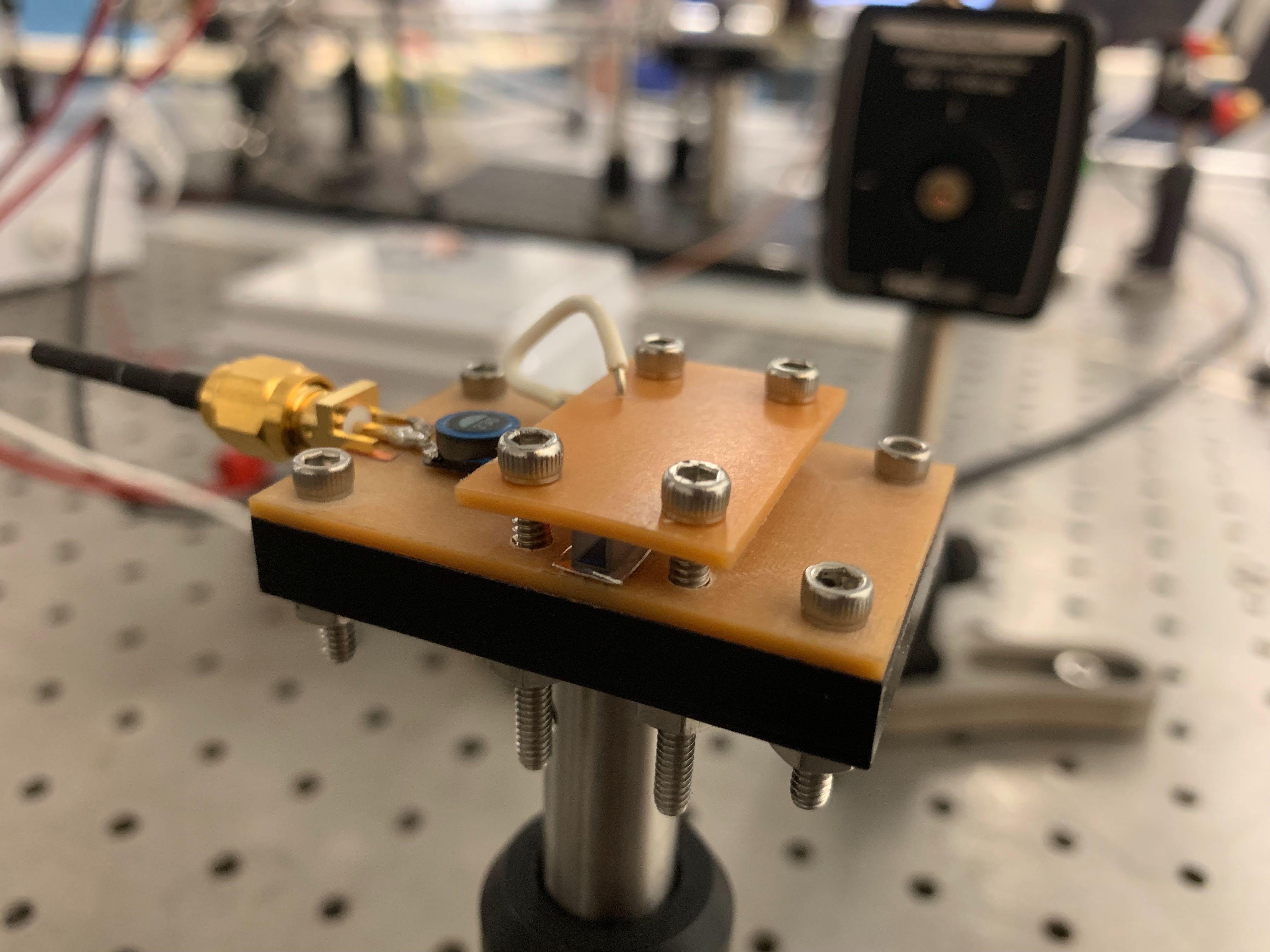
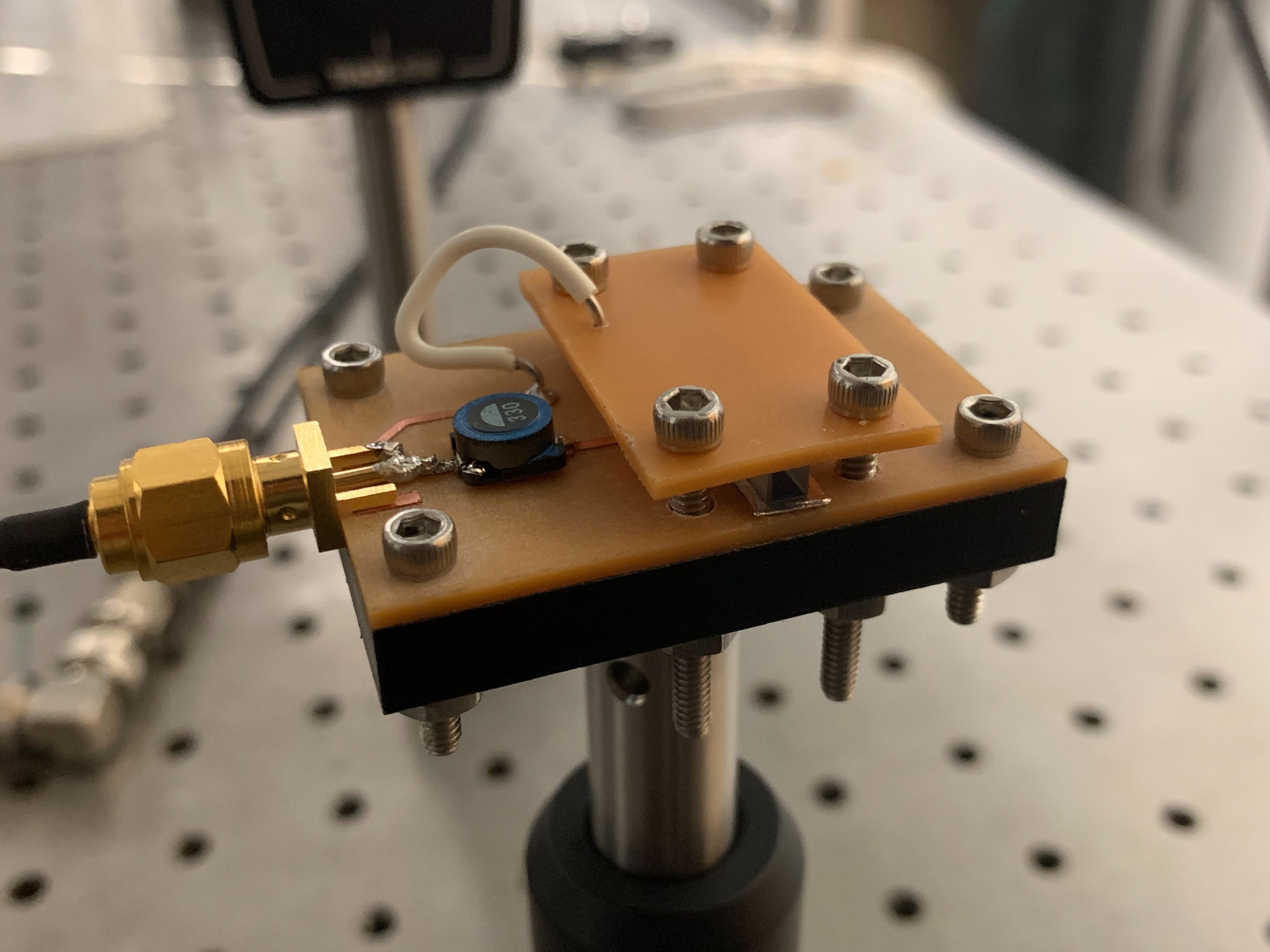
The design for this project is based heavily on work done in the Will Lab that they generously shared with us.
We chose Lithium niobate (LiNbO3). It has a good Pockels effect, so we can minimize the input voltage to achieve the required modulation depth.
| Electro-optic Coefficient | Value (pm/V) |
|---|---|
| r13 | 9.6 |
| r22 | 6.8 |
| r33 | 30.9 |
| r42 | 32.6 |
Taken from Boyd, 2003. This is within a margin of error.
The "cut" of a crystal is the direction light is meant to propogate through it, e.g. Y-Cut means light will travel in the Y direction of crystal (where the X, Y, Z directions are specified by the crystal geometry). The voltage required for a pi phase shift is determined by the cut.
Applied electric field in Z direction, wave propagates in Y direction (Y-Cut):
Applied electric field in Y direction, wave propagates in Z direction (Z-Cut):
| Value for ne | Value for no | Laser wavelength |
|---|---|---|
| 2.2666 | 2.3650 | 468nm |
| 2.2342 | 2.3232 | 532nm |
| 2.1875 | 2.2715 | 708nm |
| 2.1845 | 2.2680 | 728nm |
| 2.1702 | 2.2491 | 852nm |
| 2.156 | 2.232 | 1064nm |
We used Y-cut lithium niobate as our EO crystal. The bandwidth needed was 400nm-1100nm. We used different AR coatings to cover this range, one from 400-700nm and one from 700-1100nm. The crystal is 3mm x 3mm x 30mm, where one face is 3mm x 3mm.
| λ( in meter ) | Vπ ( in volts ) |
|---|---|
| 468 × 10-9 | 201 V |
| 532 × 10-9 | 237 V |
| 708 × 10-9 | 335.65 V |
| 852 × 10-9 | 412 V |
| 1064 × 10-9 | 524.325 V |
We used a resonant circuit to minimize the input voltage which keeps the device safe to operate and avoids the extra effort of generating that high voltage.
The resonant frequency can be calculated:
We can use the usual parallel plate capacitor formula to calculate capacitance:
Permittivity for Lithium Niobate is a tensor:
If we apply electric field in Z direction, we are going to use ε33
| Parameter | Value | Description |
|---|---|---|
| ε33 | 0.2543 × 10⁻⁹ | permittivity for lithium niobate (in F⋅m−1) (about 28~30 times larger than ε0) |
| A | 0.003 × 0.03 | area of two plates (in meters2) |
| d | 0.003 | distance between plates (in meters) |
| C | 7.629 × 10⁻¹² | Capacitance of the crystal |
We use impedance to calculate the Veom with respect to input voltage (Veom is the voltage difference of two plates between the EO crystal). Vinput is the applied voltage before the resonant circuit. Rsma is the resistance of SMA RF connector. Rload is the resistance for the circuit.
Rsma = Rload = 50 Ω
C = 7.629 × 10⁻¹² (approximately)
We need a modulation frequency f = 10 MHz = 107 Hz so we need L ~ 33.2uH
Quality factor for this circuit (RLC circuit) Q ~ 20
So the the maximum voltage required to operate is ~25 V.
There will obviously be stray capacitance and other non-ideal effects. In practice our quality factor was about 6, and our resonant frequency was ~8.7MHz.
Parts used:
- 33.2uH inductor chip
- RF Connector (50ohm)
- (2) Indium foil (~4mm x 30mm)
- Lithium Niobate crystal
- Delrin stock (to be milled, <13mm thickness is ideal)
- (8) 4-40 screws
- (8) 4-40 nuts
- (1) 8/32 screw
- (4) Spring Washers
- 8/32 compatible 1/2" optics post
- 1/2" optics post holder
First, mill the mount (generally any plastic works, but delrin was used for our EOMs). The mount design is in the repo as a fusion360 model and an stl/step model.
Second, mill the top and bottom pcbs. Set a large clearance (20 mm) when milling them such that all copper visible on the board is for required lines. The eo crystal will be sandwiched in between the top and bottom pcbs, with the indium foil as a cushion. You should then solder the inductor and the sma connector onto the bottom pcb. It is advisable to solder the top pcb to the bottom for the ground connection at this point (leaving a reasonable amount of slack on the wire used).
You then want to take the eo crystal and gently place that between ~4mmx30mm strips of indium foil between the pcbs. (Make sure the side of the eo crystal used is correct!) Finally, screw everything together -- first screw the mount onto the 1/2" post, then the bottom pcb onto the mount, then the top pcb onto the mount (through the bottom pcb). Note that we use 4-40 screws with spring washers to do so.
You should be careful not to break the eo crystal when tightening. We found that not much force is required to make electrical contact. Note that our resonant frequency on the circuit was 8.7MHz, but you could change this by changing the inductance (were you in need of a different modulation frequency).
N.B. Try to make sure the screws are tightened somewhat evenly. Uneven pressures on the crystal are most likely to break it (fixed by spring washers).


