DIY: High Voltage Range Switching Mode Power Supply for Embedded / Solar and industrial systems
This is a DIY WVR-SMPS (Wide Voltage Range Switching Mode Power Supply) or simply Tesla SMPS is a wide range and high voltage input for low power embedded systems. This device allows input voltage as low as 100 VAC and as high as 820 VAC in wide frequency range (45 − 450 Hz) or even in DC voltage as low as 142 VDC and as high as 1,160 VDC using only 3 transistors
You can find PCB version in:
AC 100 ~ 820 Volts (45 - 450 Hz)
DC 142 ~ 1,160 Volts
DC 25.8 Volts (Insulated)
AC: 46 Va
DC: 34.3 W
0.78 @ 180 VDC / 127 VAC
0.70 @ 500 VDC / 350 VAC
0.65 @ 1,160 VDC / 820 VAC
0.75
3,600 Volts
42.6 Ampères @ 1,160 Volts
0.38 A^2-seconds
1.1 mH
933 mA
- Supply for low power Embedded or Solar Systems (max. power 20W)
- Safe high insulation for output voltage (max. 3,600V)
- Limited inrush current 42.6 A @ 1,160 Volts DC (0.38 A^2.s)
- High frequency range in AC operation (45 − 450Hz)
- AC/DC operation
- Static short circuit/overload protection
- Under voltage protection
- Low cost components (only 3 active elements!)
- Startup circuit
- Limited ID (current drain) monitor
- Secondary side grounded for security
This power supply works with very high voltage input. Care MUST be taken to avoid any personal injuries or death
-
When power on high voltage, keep clear from input voltage cable.
-
For input voltages above 300 Vac/Vdc negative output MUST be grounded with 10 Ohms impedance or less
-
Keep in mind that this circuit stores high voltage even when power cord is off. If you want to repair or clear this SMPS wait at least 1 minute after remove power supply cord. Check test points TP1 (Cathode) and TP2 (Anode) pins with Voltimeter in scale 1,000 Vdc after touch or repair this circuit.
-
This device has security circuit for under voltage, short circuit and overload. When one of these events occurs, this SMPS will stop working and we need to disconnect power cord, remove the problem and then wait 30 seconds to turn on power cord again. NOTICE: NEVER touch or open this circuit if one of these events occurs EVEN if you disconnected this device from power cord.
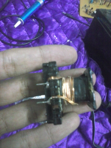
You will need to rewind the transformer following these steps
- Find an old ATX power PCB
- Disassemble the transformer core
You can use a EI or EE type ferrite core
- Take the spool out of the core
- Rewind the transformer spool
- Rewinding turns:
-
A - 4 turns (Secondary coil) (5 x 0.1 mm diameter *)
-
B - 30 turns (Primary coil) (3 x 0.05 mm diameter *)
-
C - 5 turns (Positive feedback coil) (0.1 mm diameter)
-
D - 4 turns (Control circuit supply) (0.1 mm diameter)
* Primary and secondary coil skin effect. Just interlace 3 x 0.05 mm copper wires and rewind the primary transformer spool and 5 x 0.1 mm copper wires in secondary coil
See example below:
4 x 0.1mm interlaced wire
It is EXTREMELY IMPORTANT to insulate high voltage from secundary side. To do this you will need 6 layers of insulating tape to insulate 3.6 kV. Thus:
Transformer spool cross section example:
Primary coil winding
Control circuit supply and control circuit supply
Finishing insulation
Flyback topology needs a core gap due to high peek flux to avoid saturation of the ferrite coil
So we need to create one approx. 120um core gap using a non magnetic material. E.g.: a piece of paper
Take a A4 paper
Cut a piece of paper
Fix the piece of paper in transforme core
Close the transformer core
Finally your transformer is ready to work in your Tesla SMPS
Feel free to contact me at [email protected]
This project is sponsored by PCBWay


