Home made foot pedal native USB MIDI controller device using an Arduino pro micro. The circuit schematics and drawings were made with Fritzing and the code with the Arduino IDE.
The goal was to build a footstomp pedal with many switches (10) mostly to control looping software but it can also be used like any MIDI controller (as a MIDI instrument, to control recording software). The device preferably had to be recognized as a real MIDI device so I used an Arduino with a ATmega32U4 processor which can be used to emulate a keyboard, a midi device, etc.
For example, these devices uses the ATmega32U4 processor:
- Arduino Leonardo,
- Arduino Micro
- Arduino Pro Micro (SparkFun)
- Teensy 2.0
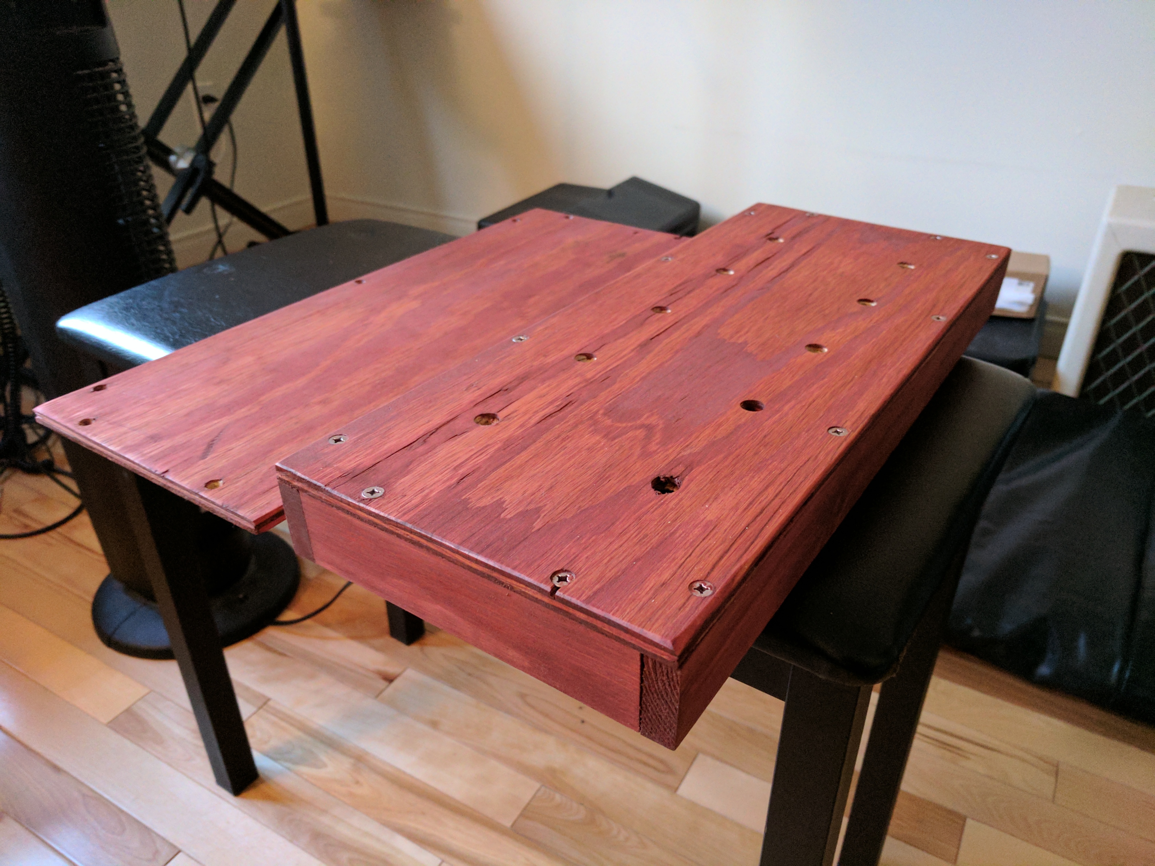
Since there are not many enclosures that are big enough to hold 10 foot/stomp switches, I built my own using pieces of wood I had laying around. I used one sheet for the top, one for the bottom part, and some larger pieces for the sides. I secured them with glue and screws except for the bottom part which is just screws to be removable.
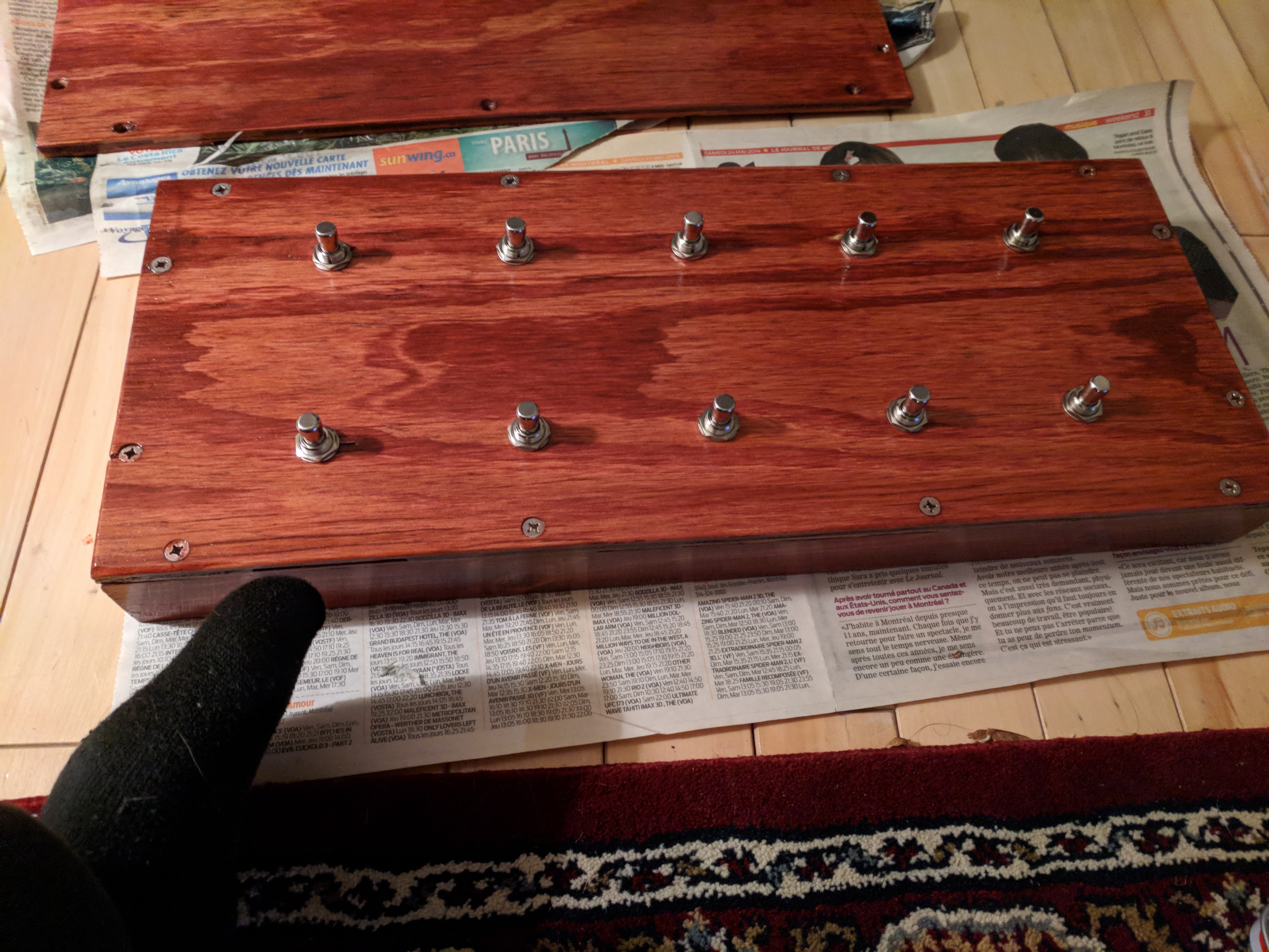
This is what it looks like once dyed.
I applied 2 layers of varnish to protect the wood:
Since I wanted to be able to use the switches as ON/OFF or as pushbuttons, I used simple SPST momentary foot switches.
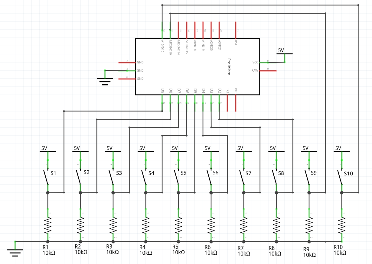
The circuit is pretty straightforward. The switches are connected from VCC to the 10 Arduino digital inputs and these inputs are also connected to the ground with pull-down resistors. Even though I believe the Arduino has internal pull-up resistors that can be actived through software, having actual pull-down resistors is a bit safer and helped for solder the components to each other.
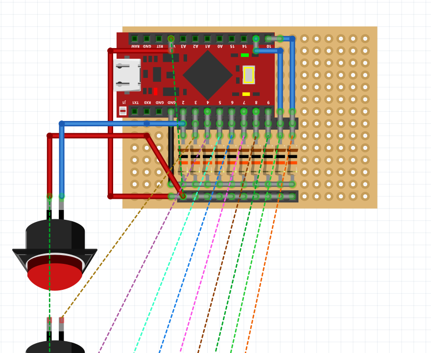
On the protoboard, it looks like this:
I used female headers to prevent having to solder the wires and the Arduino directly on the protoboard to be able to reuse the arduino or the switches without desoldering. Since the protoboard I used did not have any prior connections, the connections were made directly with the resistor legs.
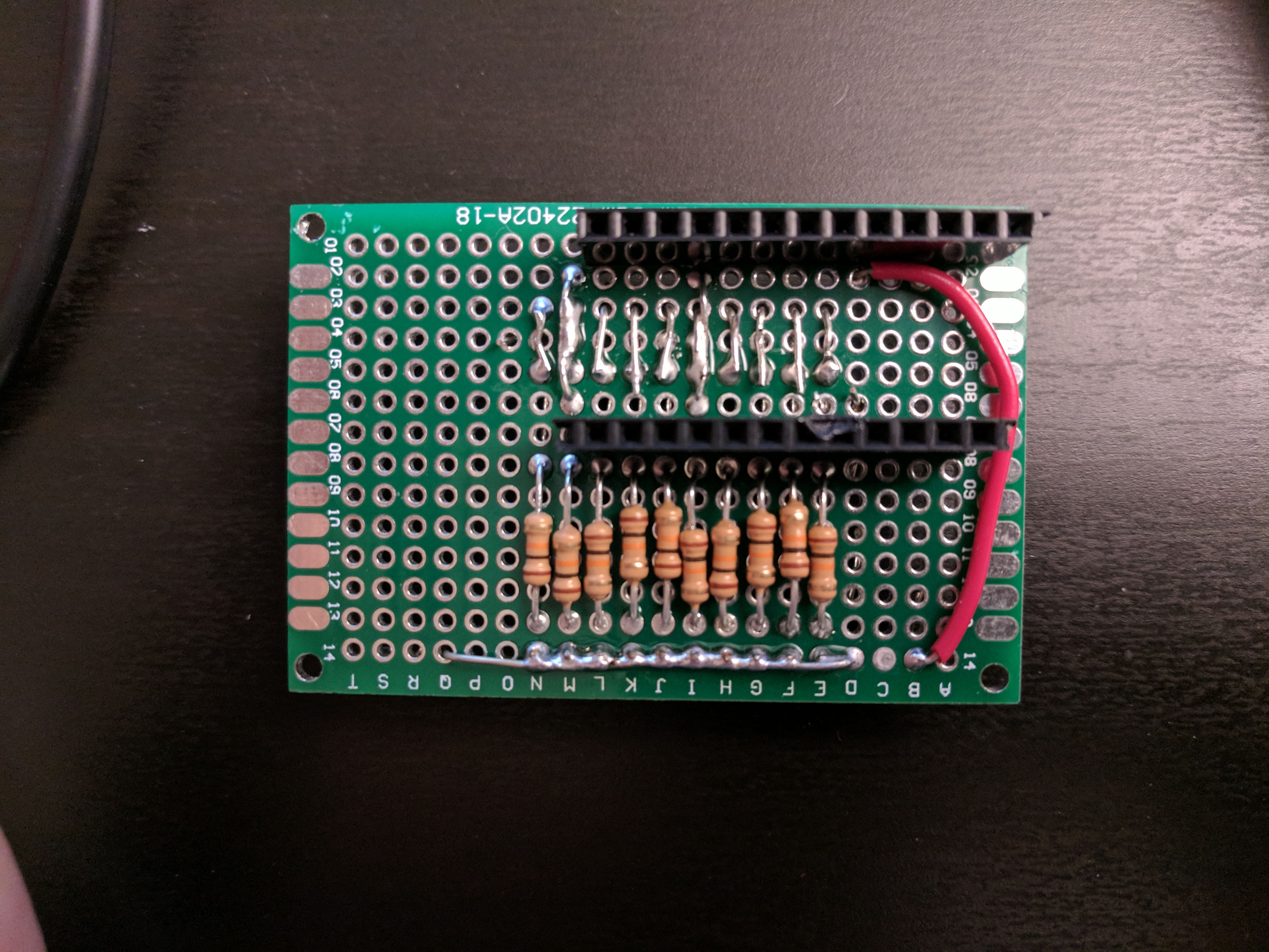
The protoboard looks like this:
Here is the soldered back of the circuit board:
Here is the soldered front of the circuit board:
Note: I realized after soldering that I forgot to solder the bottom female header and that I had planned the Arduino inputs upside down so I had to be a little creative. I soldered the input headers on the opposite side and switched the ground and the VCC of the arduino (I was lucky since the Arduino inputs are pretty symmetric). In the end the pull-down resistors just became pull-up resistors.
This is what the box looks like with switches on it.
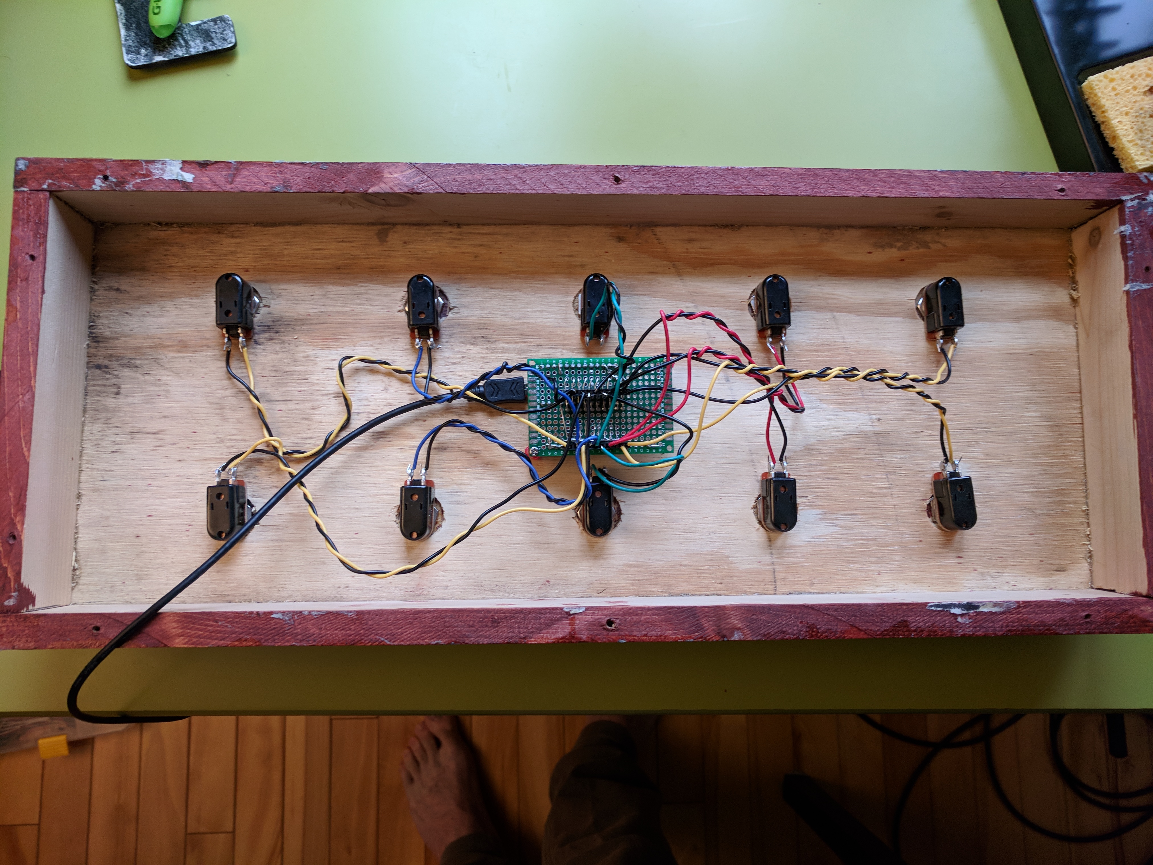
I soldered cables to the switches and just inserted the other ends of the cable in their respective ground and input female header slot on the board. Note: one can use hot glue to make sure that the cables stay still in the female headers on the board. I used a male to female micro-USB cable to expose the Arduino micro-USB port and have a longer USB cable. Here is what is looks like:
I basically just reused this MIDI device example and adapted
the code for 10 inputs. An important difference here is that I changed the pressedButtons and previousButtons bit flag
variables to uint16_t. A uint8_t was adequate for up to 8 inputs but I used 10 inputs which had not enough bits to handle
10 inputs.
