PCD8544 is a library for the Arduino to interface with LCDs based on the Philips PCD8544 controller (datasheet) or compatibles. These displays are commonly found on older monochrome mobile phones, such as the Nokia 3310 or 5110, so if you have one of these stuck in a drawer, take it out and start hacking away! :)
This library is meant to have a minimal memory footprint, small enough to be usable in an ATtiny85 with enough room left for your code. If you need graphics and other features and can spare the resources, check out the library from Adafruit.
Modified by John Greenwell to adapt driver for custom HAL support, 2024.
For this modified version, the following hardware abstraction layer (HAL) requirements must be satisfied:
- A header file
hal.hproviding access to HAL namespace classes and methods. - A
GPIOclass within theHALnamespace with the following methods:- Set pin mode:
pinMode(uint8_t mode) - Write logic level to pin:
digitalWrite(uint8_t val)
- Set pin mode:
- A
SPIclass within theHALnamespace with the following methods:- Perform SPI data transfer:
transfer(uint8_t data)
- Perform SPI data transfer:
- A delay_ms() function in the HAL namespace that delays an accurate milliseconds to be used for timing.
Some further requirements may also be found. Typically, these will mirror the Arduino framework and should be added to hal.h.
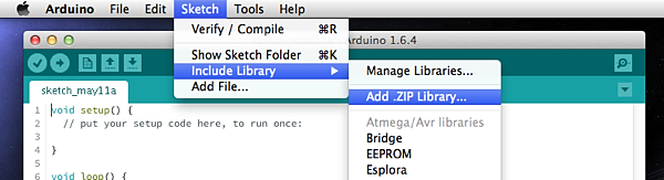
Download the latest zip file from the releases section. Then open it from the Sketch > Include Library > Add .ZIP Library... menu inside the Arduino IDE and a new "PCD8544" entry should appear in the Sketch > Include Library and File > Examples menus.
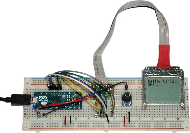
To use this library, you must first connect your LCD to the proper pins on the Arduino. For a Nokia 3310 display the connections would be the following:
| Display Pin | Arduino Pin |
|---|---|
| Pin 1 | +3.3V Pin |
| Pin 2 (SCLK) | Digital Pin 3 |
| Pin 3 (SDIN/MOSI) | Digital Pin 4 |
| Pin 4 (D/C) | Digital Pin 5 |
| Pin 5 (SCE) | Digital Pin 7 |
| Pin 6 | Ground Pin |
| Pin 7 | 10uF capacitor to Ground Pin |
| Pin 8 (RST) | Digital Pin 6 |
For this display model, "Pin 1" is the leftmost pin when facing the back of the display with the connector on top.
Nokia 5110 displays are slightly different. They have an external oscillator pin between pins 5 and 6 which should be connected to +3.3V. I haven't used one of these myself, so please see the diagrams on this page for more details.
Since these LCDs are 3.3V devices, you should add extra components to connect it to the digital pins of the Arduino (not necessary if you are using a 3.3V variant of the Arduino, such as the Arduino Pro). However, the I/O pins are supposed to be 5V tolerant, so you can get by with 1K resistors in series with each pin if you like to live dangerously.
Now, take a moment and read through the included HelloWorld.ino example.
It shows how to use the basic features of the library. There is also another
Thermometer.ino example that demonstrates bitmapped graphics and charts.
The library allows the use of custom bitmap symbols (5x8), defined by an array of five bytes. To make it easy to create custom symbols, there's a graphical glyph editor available online.