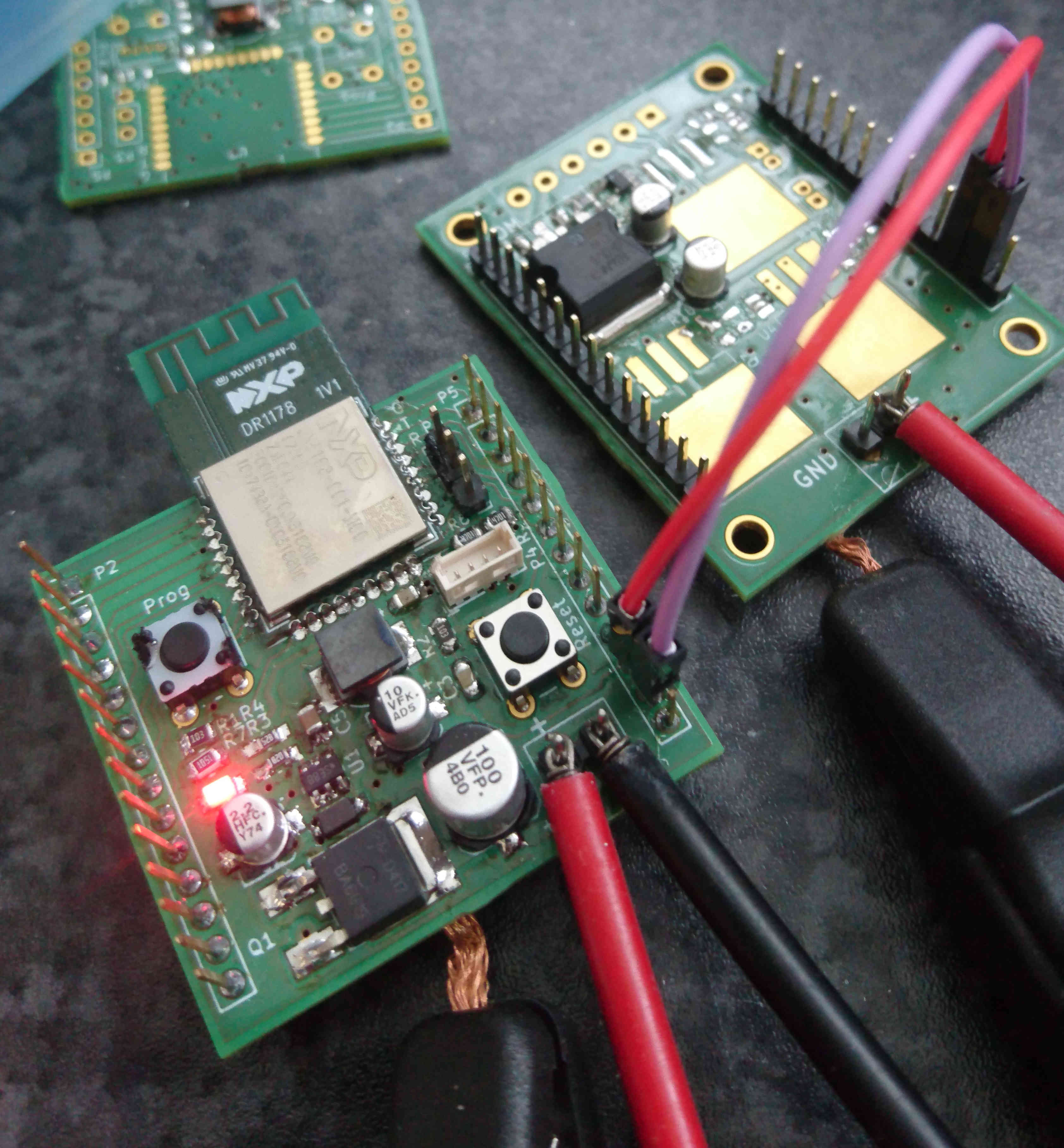
Carrier Board for JN5168 Module with Reset and Programming Button; Step-Down Regulator (24V DC input).
This is a carrier board for JN5168 ZigBee modules. All pins are broken out. Reset and Programming buttons are provided. The better part of the carrier module is occupied by parts for the step-down voltage regulator. Reverse input polarity protection is provided (except for the input buffer capacitor, if placed).
Above stated imput voltage limit (24V) depends on the FET used for polarity protection and the voltage rating of the input buffer capacitor. The chosen FET for polarity protection is rated for up to 30V. Omitting or replacing this FET and placing an appropriate buffer capacitor allow for input voltages up to the limit of the DC-DC step-down regulator, i.e. 45V.
Voltage is supplied via RIACON Connectors (screw terminals that may be pulled off from their pins).
Here is a representation created by KiCAD:
There you go, a real PCB (to the left):

On the above picture you might realize the voltage supply (red and black) is done via clamps instead of the screw terminal: This is due to the RIACON screw terminal that can just be pulled off the solder pins.

