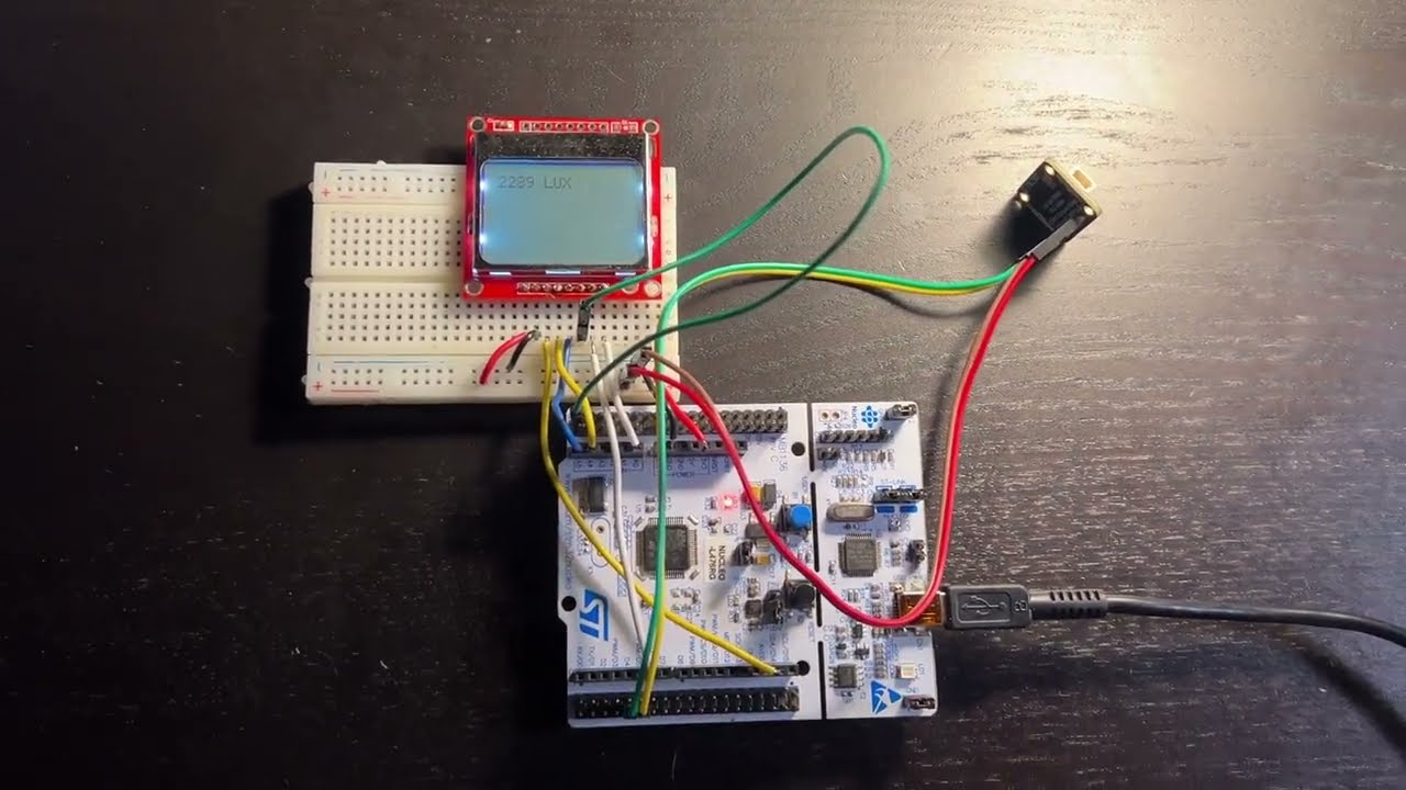
A collection of programs, built for STM32L476 microcontrollers, to measure and display light measurements.
- Built around FreeRTOS, guaranteeing no light measurements are lost or are not displayed.
- LCD driver uses SPI @ 3MHz, guaranteeing quick display of light measurements to the LCD screen.
- SPI, I2C, DMA, PWM, and LCD drivers are custom written from scratch in C.
- Nucleo-L476RG reference board
- Nokia 5110 LCD screen
- TSL2591 light sensor
make all
make install
- Use task notifications instead of binary semaphores to reduce latency and memory usage
- Use blocking takes (of notification/semaphore) that cause the scheduler to switch tasks upon blocking
- Change misc task priority to lowest WITHOUT starving it of CPU time
- Run a seperate terminal with the following command to start:
make load - Then, in a seperate terminal, run the following command to read the value of the register 0x10000000:
./readreg.sh - If you want to read the value of a different register, then change the
regvalue to your chosen memory address in readreg.sh.
- How to create applications that meet timing requirements using FreeRTOS.
- How to use Queues and Semaphores to ensure secure inter-task and inter-ISR communications.
- How to port FreeRTOS to a given MCU without using HAL/CMSIS.
- How to initialize and control SPI, I2C, DMA, and Timer (counting and PWM mode) peripherals in ARM Cortex-M4 MCUs.
- How to debug hard faults, bus faults, etc. using ARM Core registers and System Control Block registers.
- How to write an LCD driver.
- How to debug digital signals using oscilloscopes - see images below, along with explanations!
A preface: I decided to observe the signals on the Data/Control pin and the SPI bus (MOSI, SS, and SCK) to better understand how
my system was working and to be able to debug signal integrity issues in the future. To do this, I had to learn how to use the trigger
and bus features on Tektronix oscilloscopes. Below are some images and code snippets that explain the debugging process.
I used this code snippet, placed in lcd_on(), to look at the Data/Control pin's signal.
lcd_data();
spi2_write(0xFF);
spi2_write(0x11);
spi2_write(0xFF);

lcd_command();
spi2_write(LCD_SET_Y_ADDRESS(5));
spi2_write(LCD_SET_X_ADDRESS(20));

lcd_data();
spi2_write(0xFF);
spi2_write(0x11);
spi2_write(0xFF);
From this arrangement, I was able to capture the following two events:


Upon removing this code snippet from lcd_on(), the last function call invoked for the LCD screen is lcd_clear, which sends
504 bytes of 0x00 to the LCD screen via SPI to clear it's RAM. I captured an image of the SPI bus signal (as well as MOSI's decoded value) that
was caused by this code below. Note that this image (and the next) were captured using the trigger set on the falling edge of the SS signal.

- note how you can see the 0x00's in MOSI. This confirms that the microcontroller is correctly clearing the LCD controller's RAM.
Lastly, I wanted to test the validity of the lcd_all_pixels() function. I added a lcd_all_pixels() to the end of the lcd_on() function, then I
viewed the output on the oscilloscope. Note the following definitions:
The lcd_all_pixels() function has the following definition and macro:
void lcd_all_pixels(void){
    lcd_command();
    spi2_write(LCD_DISPLAY_ALL);
}
#define LCD_DISPLAY_ALL (0x09)

