-
Notifications
You must be signed in to change notification settings - Fork 4
Progress
One of the big next goals is to get feedback of the hardware. It would be very helpful to see if the machine is running or shut down. You could check and hear it from distance by pressing the clean button and press it again to stop the machine from pumping water. Obviously that is not very convenient.
Also if the water level is too low or the coffee grounds box is full, the machine would not react to any input but turning off. But like in the first example, the user is not informed by that.
One way to get feedback is to grab the LEDs' signals and convert them to the 3,3V level of the RPi. I already soldered enamelled copper wires to some testpoints of the front-panel PCB and made some experiments. Unfortunately the signals are not as easy to distinguish as expected. My last try was to read the voltage drops via the A/D converter of an attiny. That looked promising at first but did not work as reliable as needed. I think it has something to do with the LEDs' PWM control. Therefore the signal has to be filtered somehow. That could be done inside the attiny or the RPi.
Another approach (that might be easier and probably does not need any filtering) is to directly grab the sensors signals, like the water-level sensor below the watercontainer.
Everything is fitting quite nice into the spacious area next to the original electronics. I reused the original cable managment to run the power cord for the USB power-supply powering the Raspberry Pi.


My interface circuit is connected via these colorful 2,54mm grid jumper wires to the Raspberry Pi. I ordered a lot of them on ebay/china some time ago. They are available with male and female connectors in different lengths, pricing around 1-2€ for a package of 40. I also used them to connect the coffee-machine's buttons to the interface circuit. Therefore I cutted them and soldered enamelled copper wire to them (see below).


All the parts soldered to the PCB. Unfortunately, I did not route one of the ground lines. That is why there is a small pice of enamelled copper wire running at the lower edge of the PCB. I did not solder any smd stuff before this project. But it worked pretty good with the help of flux! I applied a mixture of colophonium and ethanol to the PCB and used my standard soldering tip with 1mm solder and somethin around 330°C. I put some sockets to the PCB for the optocouplers because I did not want to heat-stress the stuff inside of them too much.

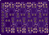
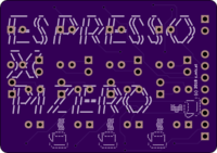
Front and back view of the PCBs. I really like the printing quality!


The components labels placing is not really helpful and sometimes not readable but my focus was to save as much space as possible. Anyway, not a big deal. I will solder it with my PCB software openend ;-)
The PCBs are delivered!

Ordered: 18th February
Shipped: 27th February
Recieved (Germany): something around 6th March
Finally I designed the PCB of the interface circuit. Luckily oshpark has a good documentation for accepted PCB-files from different softwares, so I picked one of these softwares. After some youtube-videos I was able to design my PCB in KiCad. Despite of rearranging everything nicely there aren't any big changes to the prototyped circuit. In my final iteration of the PCB, I changed the resistors and transistors to SMD parts. Otherwise the cost for my order would have been doubled. Now it is 12$ for three PCBs

I don't know if I am able to solder SMD parts with my big solder tip, maybe I will order some smaller ones.
Also I got some meters of enamelled copper wire to replace the quite thick wires I soldered to the interface before.
I used the 0.3mm one. Now there is nothing interfering with the buttons anymore and the diameter is smaller than the SMD parts on the circuit. Everything fine!
The soldering looks a little bit messy because I like to use a lot of flux.
Now it looks much cleaner than before. I taped the wires to the original flat cable to enhance the sturdiness of the cable harness.
That is the actual side-view right now. I won some space because of the better cable management, but in general it looks like before.
First espresso via webbrowser! Sorry for the jumpy filming, was a little bit excited :-D

Setting GPIO Pins via webbrowser with Flask. The Raspberry Pi and the laptop are connected to my local wlan:

Yesterday I got my order of optocouplers, transistors and other stuff. I made a litte circuit to drive two channels / switches via GPIO Pins. So it can control two buttons. For my tests I connected them to the power button and the espresso button. The final layout will be produced by some PCB manufacturer.

First test of the hacked frontpanel via "hotwiring" the buttons:


Here is the place where the Raspberry Pi and the interface circuit is planned to stay at. This looks like a safe place for electronics (you have to be aware of humidity) because the mainboard of the machine is placed there, too.

There is a hole for the original flat wire which is big enough for my hacked wires.
I will have to rework the running of the wires a little bit because right now the button press feels softer than before. Meaning, the wires are pressed down by the plastic grid, eventually causing damage to the isolation in the future.

First step is finished with soldering jumper cables to every switch. I planned to do the same with the LEDs for reading out the machine's status and errors but the SMD-LEDs are pretty small and my solder tip seemed to big for proper soldering. You can see them some of them (DL3 - DL5) in the first row of the circuit board.
The frontpanel looked very spacious at first, but there is a grid of plastic under the buttons giving minimal space for running the wires. This plastic construction is for transfering the mechanical force to the actual pushbuttons on the circuit and manages to transfer the light of the SMD-LEDs to the front. So if you really mess up, the buttons stop working, the LED's light will be blocked and the case of the frontpanel will not close anyway. You could cut the grid a little bit, but I wanted to modify the machine as little as possible.


