DIY Battery Charger, 12V Input, 0-25V Output, 5.5A, using AVR With these components the charger is limited to about 120W and maximum input voltage of about 15V
See also: http://mlaiacker.no-ip.org/Modellbau/AVR-Lader/
| Type | Cells |
|---|---|
| LiPo | 1-6 |
| LiFe | 1-7 |
| NiMh/NiCa | 1-16 |
| PB | 1-6 (2-12V) |
| Programmable Power Supply | 0-25V 0-5.5A |
| Parameter | Value |
|---|---|
| Input Voltage | 11-15V |
| Output Voltage | 0-25V |
| Voltage Resolution | 0-13V 14mV , >13V 27mV |
| Output Current | 0-5.5A |
| Current Resolution | 6.6mA |
| Power | up to 125W |
| PWM Switching Frequency | 31.25kHz (16MHz/512) |
| PWM Resolution | 9 Bits |
| Efficiency | up to 89% |
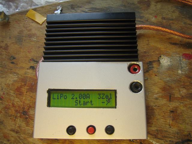
MAX-Lader with big heat sink which not really necessary.

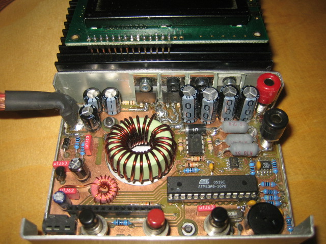
The charger without the LCD and enclosure

The electronics are mostly thru hole and optimized for home production double sided PCB. The output voltage and current is regulated using a buck/boost converter which is software controlled by the AVR. The main coil is self made which is easy. The electronics fit nicely into the enclosure but the space is limited that is why there is no balancer electronics included. The LCD should be 2x16 (HD44780) characters with 14 or 16 pins on the lower left corner. The MOSFETs and diode have to be mounted electrical isolated from the enclosure/heat sink. Mounting the Mosfets behind the output caps is a bit tricky. The output caps have to be LowESR types. The resistors for the voltage dividers for the output and current should be 0.1% types to ensure the correct voltages when charging LIPOs. The input is reverse voltage protected but the output is not. Output caps will blow when a battery is connected the wrong way.
Using bigger or more MOSFETs and bigger coil and smaller shunt resistors should enable more output power. The maximum input voltage is limited by the ICL7667 max. voltage and max. GS-Voltage of the P-Channel Mosfet (IRF4905)
The Software is heavily optimized for size to fit in the ATmega8 that was originally used. It can be build for the ATmega8 or for the newer ATmega168. Using the ATmega168 will enable some more functions like display of data from a Robbe Top Lipo Equalizer 6S when connected to the serial port. The menu is in German but very easy:
Step 1: Select battery type
Step 2: Set Cell count
Step 3: Set Current
Step 4: Connect battery (charging will start automatically when a battery is connected)
There is no ISP connector on the PCB so you have to program the bootloader before installing the AVR to the charger. The bootloader is activated when the middle button is pressed during power up. The program can be loaded using the serial interface using stk500v1 protocol with avrdude.