Zebra, adjustable column stagger keyboard
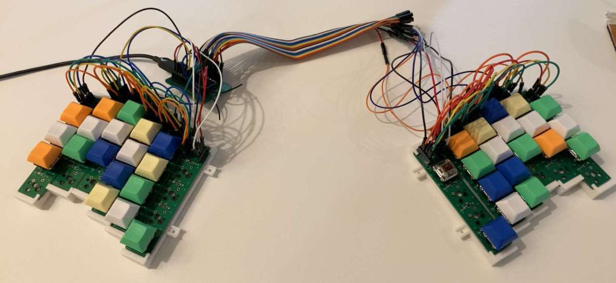
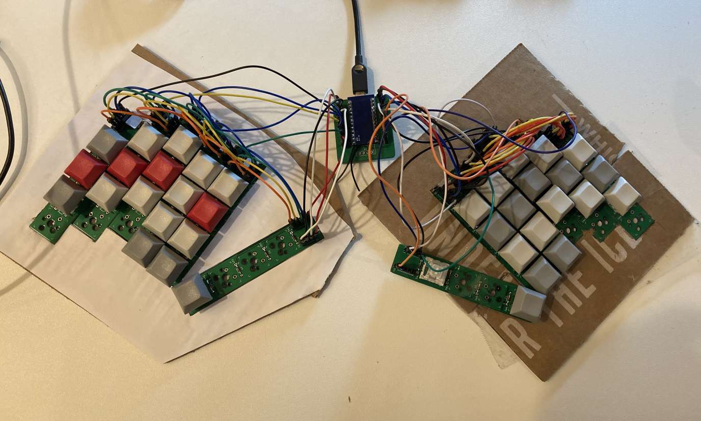
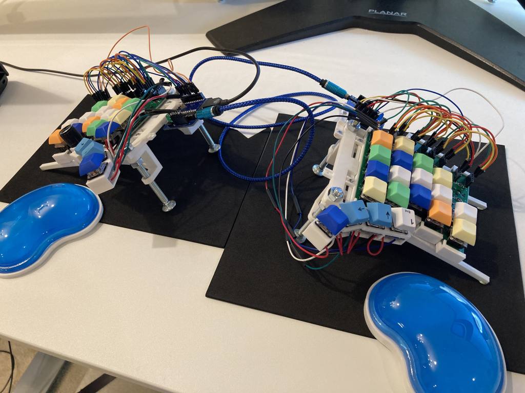
Zebra is a column staggered keyboard with independent PCBs for every column, allowing them to be put together in different positions or combinations without remaking any components or resoldering.
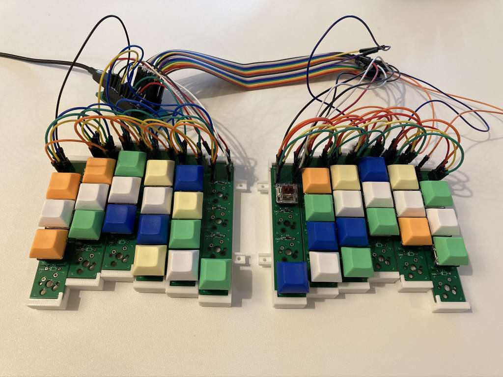
For pictured configuration:
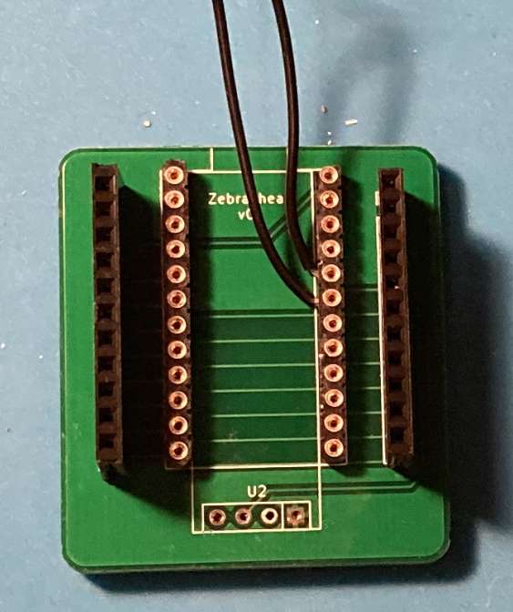
- Zebra head PCB x1 (see KiCad and gerbers)
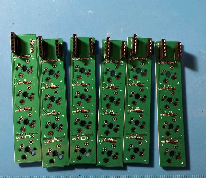
- Zebra stripe PCB x12. Up to 14 are supported, adjust other part counts accordingly if using more or less
- ProMicro, Elite C or equivalent x1
- ProMicro socket x1 (optional, I used https://www.digikey.com/en/products/detail/mill-max-manufacturing-corp/315-43-164-41-003000/1212143)
- 1N4148 diodes in through-hole package x48 (for example https://www.digikey.com/en/products/detail/1N4148TR/1N4148FSCT-ND/9356376?itemSeq=341430044)
- Kailh hotswap sockets x48 (optional)
- Single-line jumper wire headers x122 pins (remember every cut of header stripe means losing a pin. I bought 4x https://www.digikey.com/en/products/detail/chip-quik-inc/HDR100IMP40F-G-V-TH/5978200 and barely had any left. Get extras!)
- M/M jumper wires x65, at least 18 of them longer than 5 inches
- M/F jumper wire extender with at least 11 pins x1 (optional, to place the keyboard halves wider)
- Cherry MX switches and 1U keycaps of your choice x48
- Some way of holding the stripe PCBs in place: cardboard and sticky tape, or 3d printed enclosure, or anything else you come up with
- M2x5 screws and M2 nuts x20 (if using the 3d printed enclosure)
-
Solder the ProMicro socket. Make sure to do it on the right side of the PCB depending on the way the pins on your ProMicro are oriented (Pin 1 is square on the PCB). My ProMicro has pins soldered so it's mounted upside down, with the MCU facing downwards
-
Solder the jumper headers on the same side
(ignore the wires in the picture)
Solder the diodes, switch sockets and jumper headers
You can skip soldering the diodes and sockets if you're not planning to use some switches (lower left).
Here's how the wires must be connected:
-
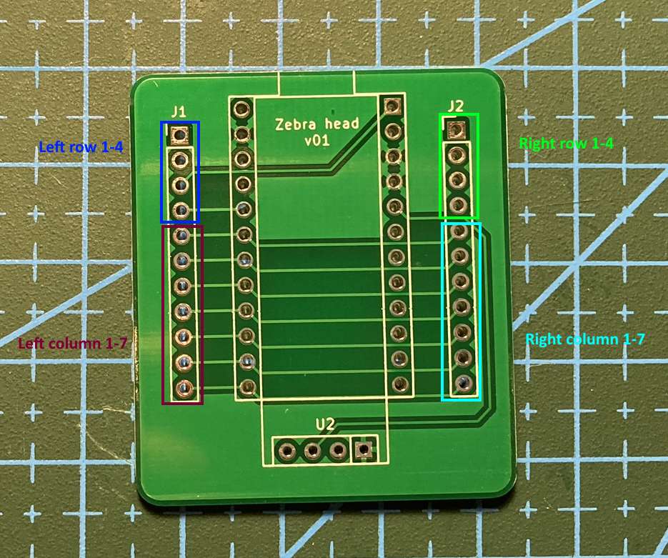
Head
Note that the row wires are different between the left and right sides, don't connect them to each other!
-
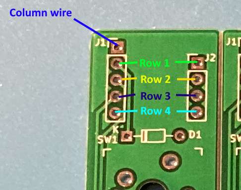
Stripes
-
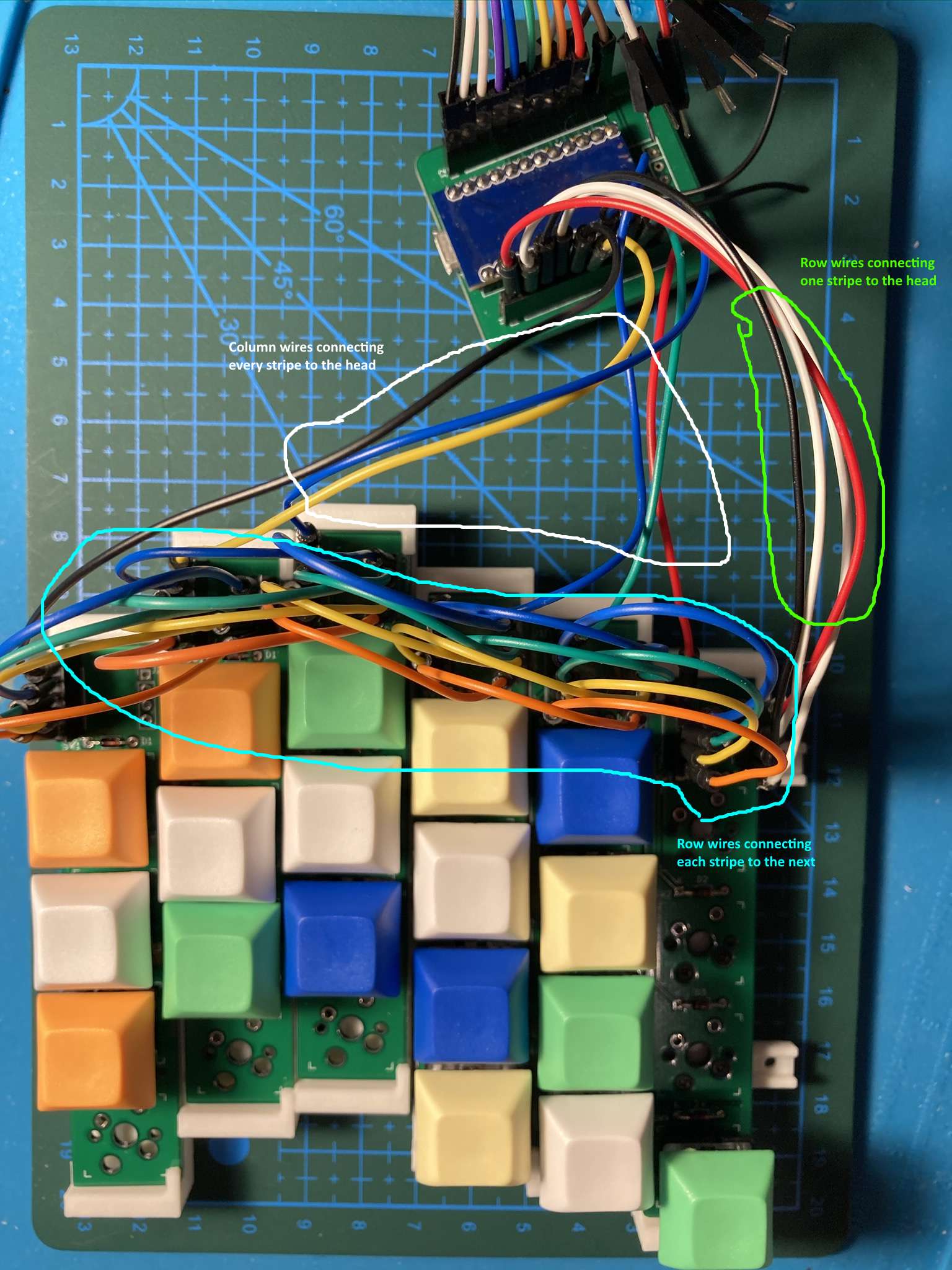
Overview of connections:
-
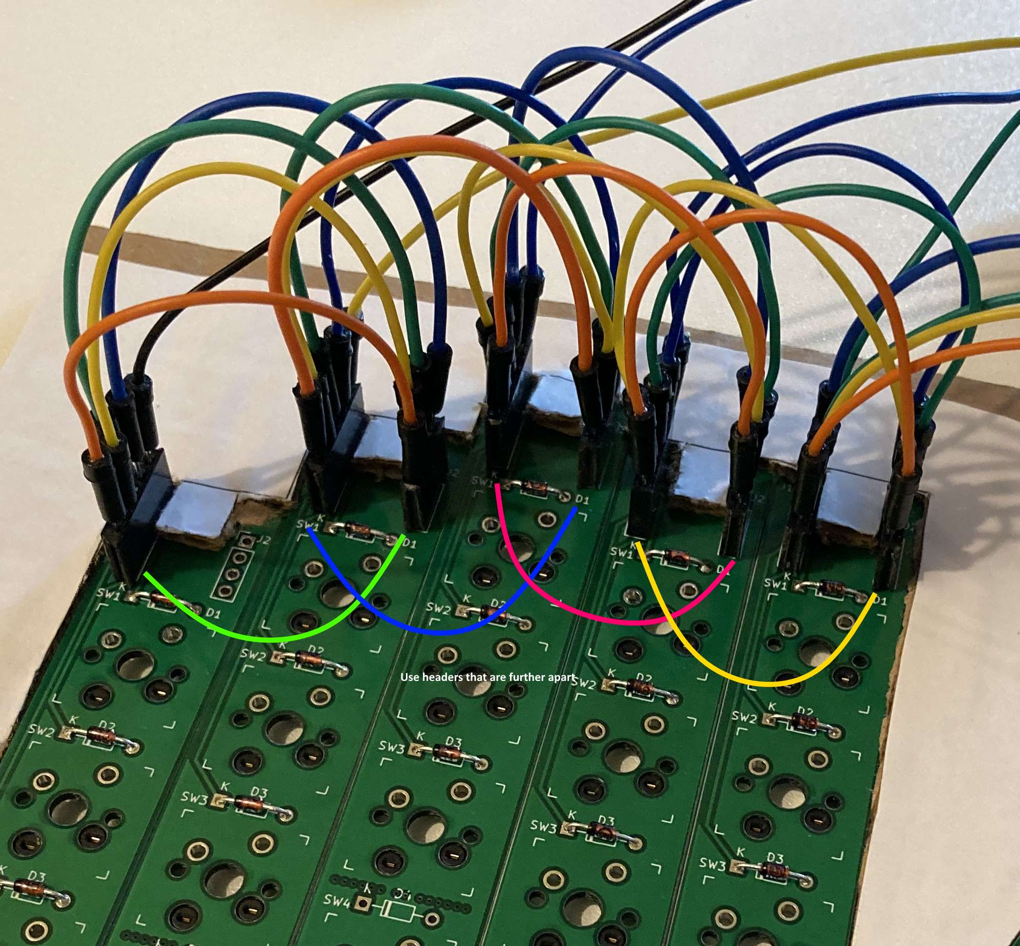
When connecting row wires between stripes, use the headers that are further apart so that the wires don't need to bend as much when the columns are arranged next to each other:
Now the difficult part - putting the stripes in place.
-
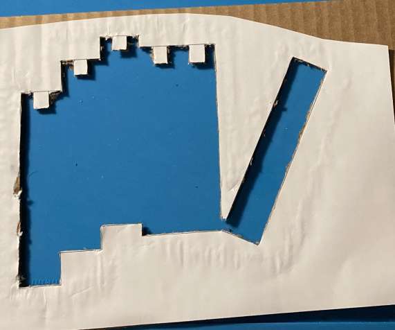
Option 1: cut the shape out of cardboard that you want to place the stripes in, put some sticky tape at the back (glue side up), and stick the column boards to it:
A template is available in cardboard.svg file.
-
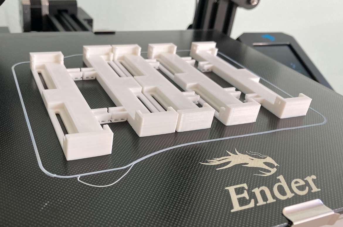
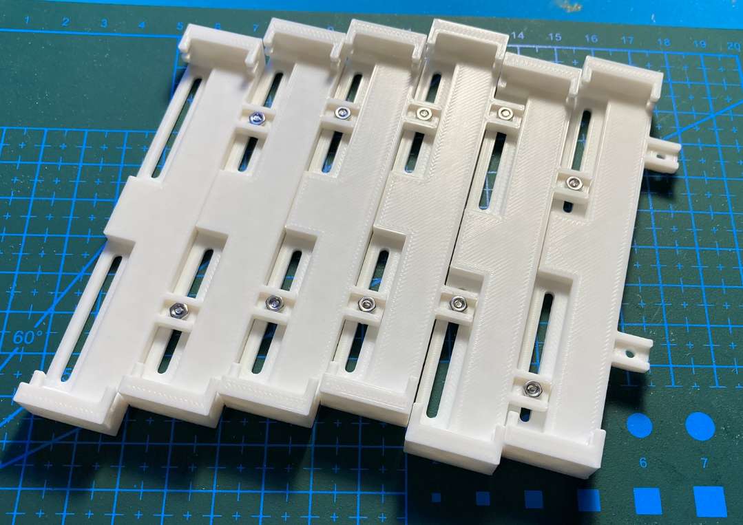
Option 2: 3d print stripe holders, screw them together and insert the stripe PCBs:
Note that a stripe allows changing stagger between 10mm in one direction and 20mm in another. Mirror half the stripes to flip which way gets more stagger on different sides of the keyboard.
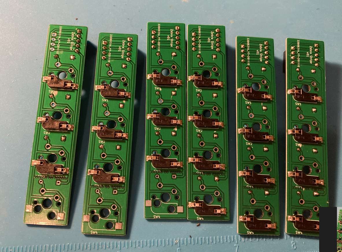
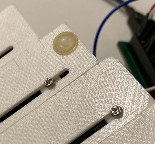
A basic ruler is built into the bottom of each stripe to measure the column stagger:
Zebra is running QMK, see the source code under the QMK folder. Copy the zebra folder under the keyboards folder in your QMK environment to compile. You can use JSON layout files made for Corne (LAYOUT_split_3x6_3) to build your layout in QMK configurator.
Try some popular or crazy configurations and see what you like!
Here's some examples:
- Let's split: no stagger
- Corne: index finger +2.4mm/middle +2.4mm/ring -2.4mm/pinky -4.8mm
- Kyria: +2.5mm/+6.5mm/-6mm/-12mm
- More aggressive stagger: +2.5mm/+10mm/-5mm/-14mm
- Tenting, encoders, true split and more in v2!
