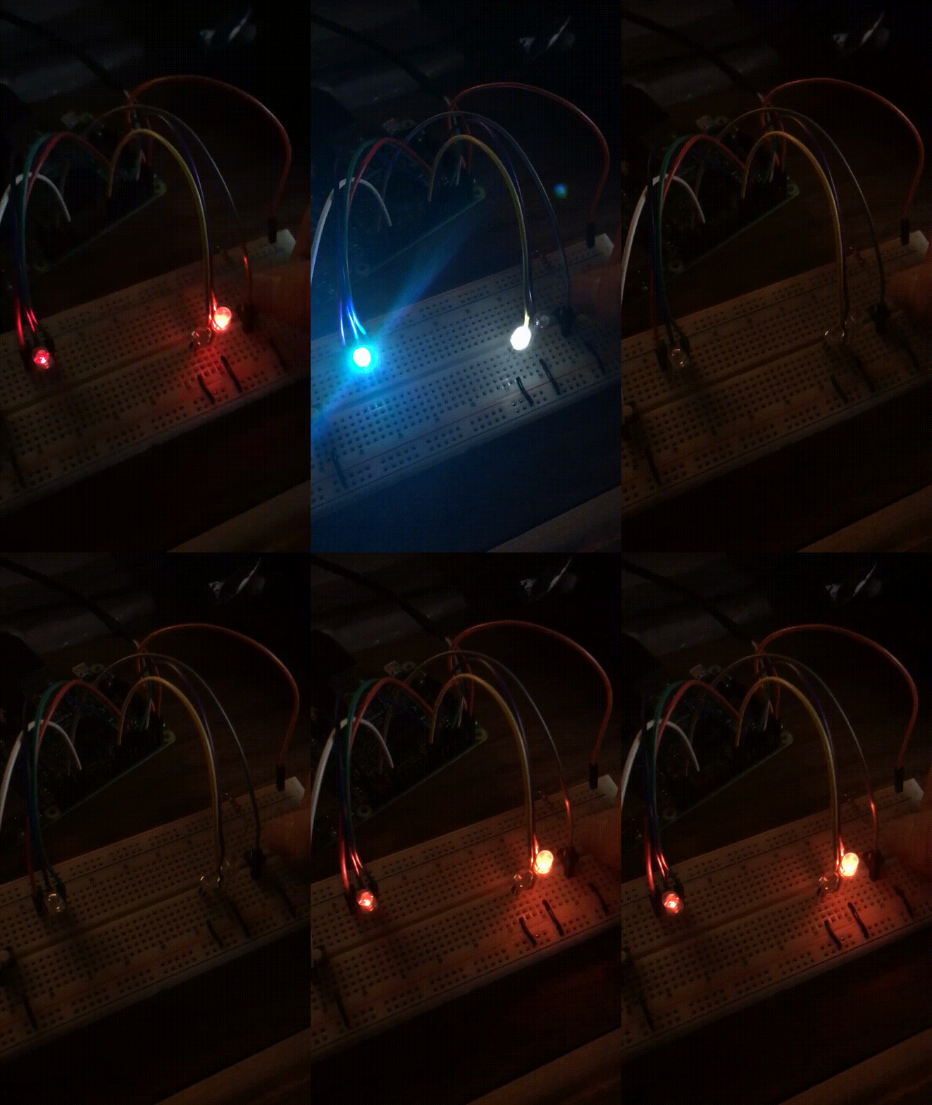
Various control panel simulations built with a Raspberry Pi along with various hardware.
Current implementations are built on a Raspberry Pi 3 Model B with 1 GB of RAM and loaded with NOOBS.
To make circuit building easier, unless otherwise stated, assume that the two positive channels and two negative channels are connected on the breadboard.
C program integrated with hardware that simulates a pedestrian cross walk with LEDs and Buttons.
Shows both possible implementations with a RGB LED as well as separate Red and White LEDs.
Hardware Used:
- 2x Resistors
- 1x RGB LED (interchangeable with 1 Red and 1 White LED)
- 1x Red Led (interchangeable with RGB LED)
- 1x White Led (interchangeable with RGB LED)
- 2x Tactile Push Buttons (other button options are also usable)
- 9x Male to Female Wire Jumpers
- 7x Male to Male Wires/Wire Jumpers
Note: Remember to adjust the number of wires with different LED/Button configurations.
Most Male to Male wires are used for grounding and therefore do not have to be very long (in fact, shorter ones may be easier to use).
GPIO Pin Usage/Implementation:
| Pin No. | Connected Component |
|---|---|
| 0 | RGB LED - Red |
| 2 | RGB LED - Green |
| 3 | RGB LED - Blue |
| 4 | Red LED |
| 5 | White LED |
| 26 | Tactile Button #1 |
| 27 | Tactile Button #2 |
Timing Information:
| Signal | Time |
|---|---|
| Walk (White) | 2.5 seconds |
| Flashing (Red) | 0.5 seconds each, total 5 seconds (5 flashes) |
| Stop (Red) | Indefinite, until button is pressed |
Compiler and Execution Information:
gcc -std=c99 -o crosswalk crosswalk.c -lwiringPi -lpthread
./crosswalk
Dependencies:
- WiringPi
Installing WiringPi:
WiringPi is a set of libraries that allow you to use the GPIO pins on your Pi to communicate with the breadboard.
sudo aptitude install git-core # only necessary if you need to install git
cd wiringPi
./build
