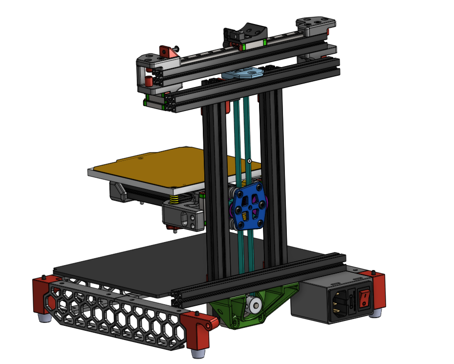
This is a high-resolution differential pulley system belt mod for the Z-axis on Voron 0 with optional Kirigami Bed support. There are quite a lot of belt mods out there, but this one differs significantly in how the mechanical advantage is implemented to achieve the same (or better) gearing ratio (notice the lack of an 80T pulley).
NOTE: This is an alpha version and heavy work in progress! Things are mostly tested and working, however there WILL be road bumps ahead and a Voron-style instruction manual is not available. Use the interactive 3D Model on Onshape below for assembly help. Please read this README carefully and in its entirety.
See at Onshape | Demonstration Video
A differential pulley system! It is a long known pulley system for achieving extremely high mechanical advantage using just pulleys and a belt. See the Wikpedia article for more information on how this pulley system works. In this case, I split up the central shaft (connecting the two unequal pulleys) into two shafts and connected them with a small belt. This way we eliminate the belt crossing.
I wanted a V0 Belt mod, that eliminates the 80T pulley for stepping down the motion and increasing torque that is used in all other belt mods. Also achieving relatively high mechanical advantage is no problem for differential pulley systems. In the differential pulley system, the "gear ratio" is integrated in the belt system. In this case, the two double pulleys have a combined teeth ratio of 27/33. Taking the Wikipedia article as a base, the following formula was derived to calculate the mechanical advantage in this system:
MA = 2/(1-r/R)-1 = 2/(1-27/33)-1 = 10
With the 20T motor pulley (2mm pitch, i.e. 40mm per revolution), this achieves a 40mm/10=4mm per revolution Z-axis advance or 0.01mm per stepper half-step with a regular 1.8° stepper motor.
Also the mechanism looks cool and is underrated. When you press me hard to find an advantage of this mod, I think this mod has less (special) parts than other belt mods.
NOTE: Theoretically gear ratios of 16 or 32 are possible with combined pulley ratios of 30/34 or 31/33, respectively. With a 16T pulley this allows a resolution of 2mm or even 1mm per revolution.
For the Kirigami bed, you need to drill two extra 3mm holes for the two screws acting as the two shafts. Print and mount the drill-guide from the STLs to your Kirigami bed and drill in the designated holes with a 3mm drill bit. If your bed is made from Aluminium, you can deburr the drill-exit wound with a sharp exacto-knife.
You need the following extra parts (this list is probably incomplete):
- 20T pulley for stepper motor
- 20T toothed idler (with bearing ID 3mm)
- 2x M3x40 BHCS (M3x30 BHCS with Kirigami Bed)
- 5x M3x16 BHCS
- 3x M3x6 BHCS
- 4x M3x8 BHCS
- 22x 0.5mm shim washer
- A bunch of heat-stake inserts
- 2GT belt 112mm (110mm also possible when changing to 27/26 and 26/33 pulleys, contact me in this case)
- 2GT belt 500mm
This repository is highly work in progress, the following things are still not satisfying:
- The endstop is actuated by the flange of one of the F623 bearings. Not nice but works for now.
- Documentation/Images on how to assemble
Feel free to use, open issues or leave alone :-)
Unfortunately I could not get a very linear motion out of this system yet. I recorded Z movement with a dial test indicator in 0.1mm increments and the accuracy is only around +/-50 um (worst case). I think this is not enough and is probably due to the belt, that "pulls" the bed up being fed through multiple (3d printed) pulleys. In fact, both small pulleys and the belt-length can be found as a periodicity in the Z position error (even with original Gates belts). That is why I currently do not recommend this mechanism for the Z-axis drive.
