Guide to flash Tasmota firmware into WT32-ETH01
- OS: macOS. For Windows please refer This.
- ESP32 Ethernet board: WT32-ETH01 v1.2.
- USB to UART Converter board.
- Tasmota firmware version: 9.5.0.
- ESP Tools.
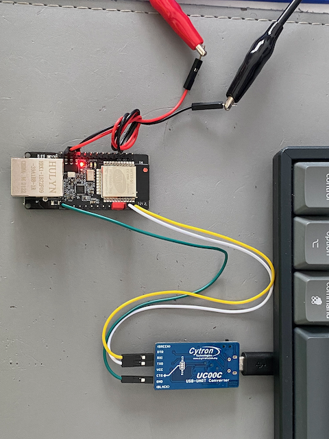
- Yellow: TX0, transmit data pin.
- White: RX0, receiving data pin.
- Green: connect to GND pinf of "USB to UART converter" board.
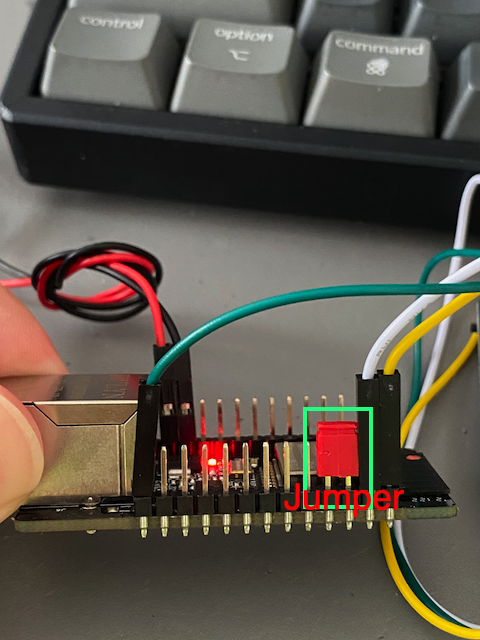
- Red Jumper: IO0 + GND, short these two pins to make WT32-ETH01 enter programming mode.
- Red: connect to external 5V (positive) power supply.
- Back: connect to external GND power supply.
- 5V connection to external power supply.
- Uart and jumper connection
-
Follow the hardware connections described above and connect the jumper.
-
Power up the board, and the red LED on the board should light up.
-
Download and copy the files from here to your local folder.
-
Goto the folder you copied, and run the following command, you need to change "/dev/cu.usbserial-1431310" to your own port number.
esptool.py --chip esp32 --port /dev/cu.usbserial-1431310 --baud 115200 --before default_reset --after hard_reset write_flash -z --flash_mode dout --flash_freq 40m --flash_size detect 0x1000 bootloader_dout_40m.bin 0x8000 partitions.bin 0xe000 boot_app0.bin 0x10000 tasmota32.bin
-
After loaded the Tasmota firmware, if successful, you should see the message similar to the following.

-
Remove the jumper, then power off and power on to the WT32-ETH01 board. Follow this guide and access to the Web UI
-
In the Web UI, go to [Configuration]->[Configuration Module] and select the module type "WT32-Eth01" as shown below, then click save button and wait for auto restart.
- After restarted, on the main page of the Web UI, click [Information] button, if your Ethernet/LAN cable is connected, you should see the following. If the Ethernet/LAN cable is connected but not the Ethernet information is not displayed, please refesh your Web UI.
- The Ethernet indicator should light up.


