Badge code and instructions for the 2018 NOLA Mini Maker Faire VIP Badge Kit
You can purchase your VIP tickets for the 2017 New Orleans Mini Maker Faire at: https://www.eventbrite.com/e/new-orleans-mini-maker-faire-2018-tickets-39528726485
This kit is included with the purchase of the VIP ticket. One kit per VIP ticket.
Be creative! The components chosen for this design were picked with the intention that you would want to customize your badge to make it your own. Paint it, stain it, change the program, add more components, etc.
The following components are included in the 2018 VIP Badge Kit:
- Arduino Pro Micro with ATmega32U4 5V/16MHz
- White 128X64 0.96 inch OLED with SPI
- 3 x AAA Battery Pack
- Blue 5mm LED
- 1k Ohm Resistor, 1/4 W, 5% (qty. 3)
- Surface mount switch (qty. 2)
- Piezo speaker
- Custom designed PCB
- Laser cut top piece
- Bots and nuts (qty. 2)
- Neck lanyard
Gather these tools before starting on your build and it will go much smoother! With the custom designed PCB, there's less wires to get in the way and hooking everything help will be easy.
- Soldering iron and solder
- Hot glue and gun
- Flush cut wire cutters and/or wire stripper
- Micro USB cable
- Computer with the Arduino IDE loaded
- (optional) Blue tack to help hold pieces while soldering
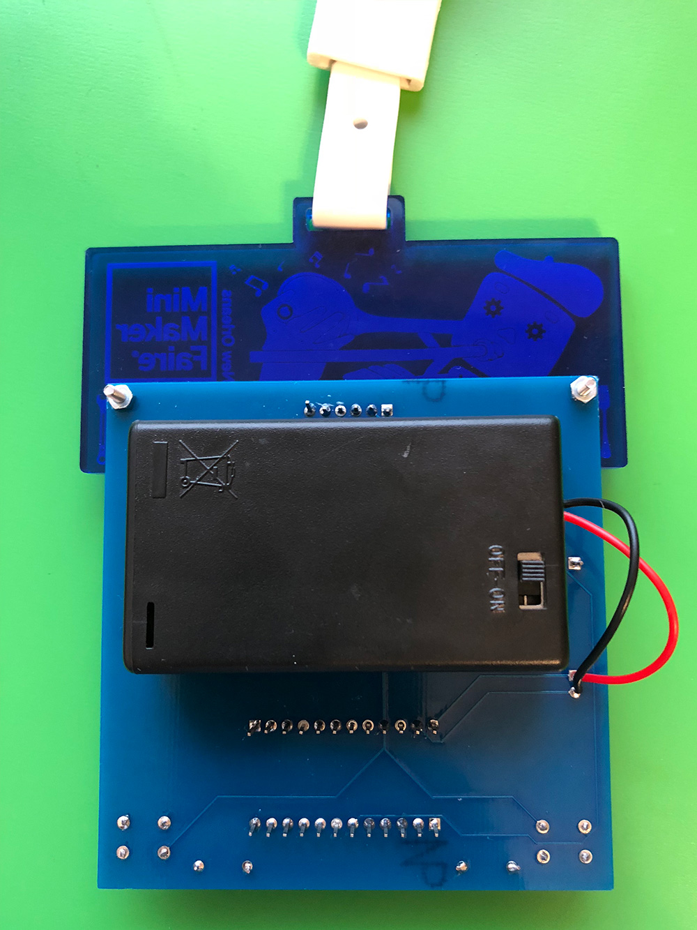
| Front Side | Back Side |
|---|---|
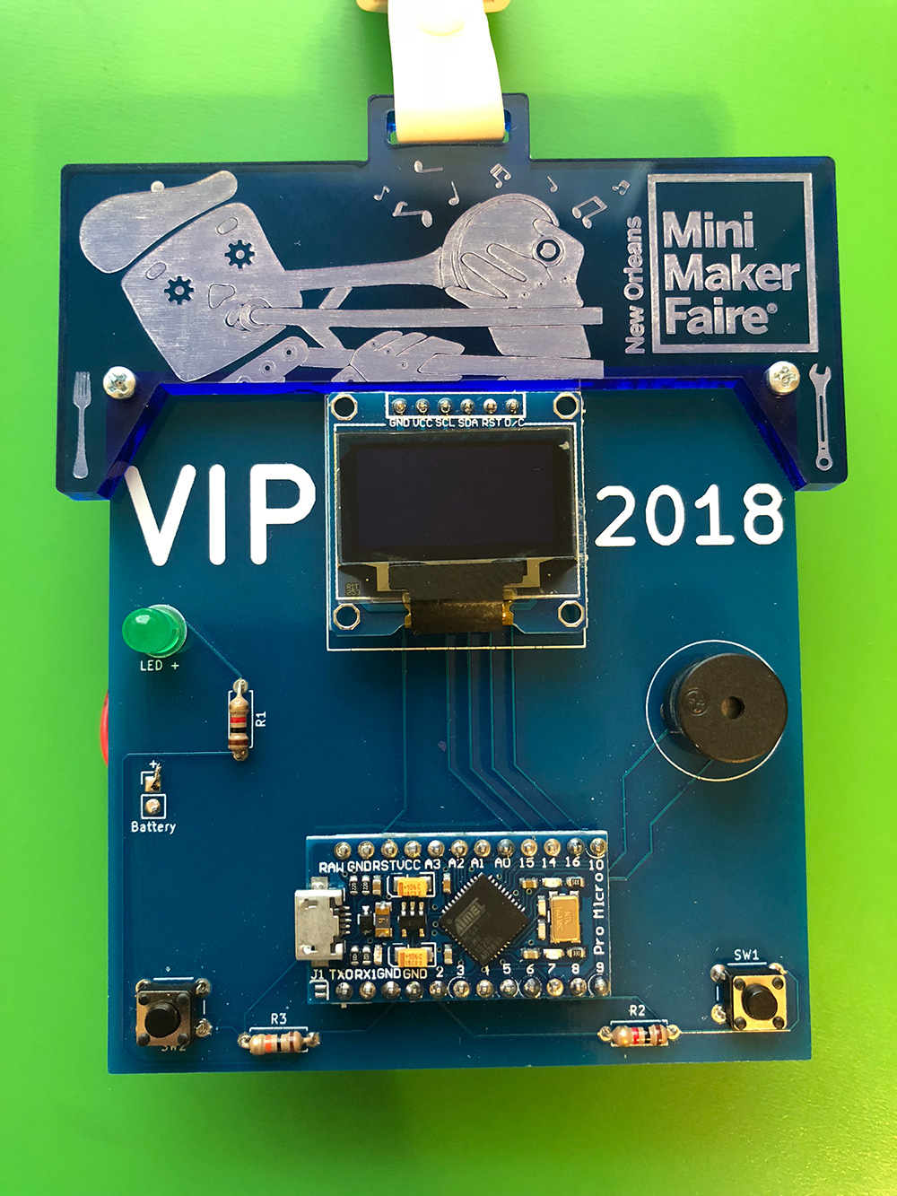 |
 |
Please read and review before starting your build.
- Pay attention to the positive and negative leads on the LED and speaker components
- On the LED, the longer lead is positive, the shorter lead negative
- The leads on the speaker will need to be bent in order to match up to the holes
- The resistors can be mounted in either direction
- The switches should mount with the pins exited the left and right sides
- Use blue tack or helping hands to help mount the included header pins
- The longer side of the pins should go through the PCB. These can be soldered to on the reverse side for expansion
- Once the headers have been soldered, you can solder on the OLED and Arduino
- The OLED screen will "float" above the PCB. You can use some hot glue under the OLED to help secure it if needed
- Use hot glue to mount the battery pack with the switch facing out.
- Trim the red and black leads
- Your red lead will be positive, the black lead is negative
- Use the supplied bolts and nuts to secure the top piece
- Be sure to remove any backing paper from the top piece
- Attach the lanyard and we'll see you at the Faire!
There are two libraries required to make the LCD work. You'll need to download each and stores them in your Arduino library so the compiler can find them when you compile the code.
- Download: https://github.com/adafruit/Adafruit-GFX-Library
- Click the green button for "Clone or download" and choose "Download ZIP"
- Once you extract the ZIP file, you'll want to place the entire unzipped folder in your "libraries" folder which is in your Sketchbook location
- In the Arduino IDE, you can find your Sketchbook location by going to File -> Preferences (on Windows) or Arduino -> Preferences (on Mac)
- Follow these same steps for: https://github.com/adafruit/Adafruit_SSD1306
- Open the file "Adafruit_SSD1306.h" in the SSD1306 library folder you just placed
- Pro tip: On Windows, use Wordpad and turn on word wrap, on Mac, open the file with TextEdit
- You want to make sure the line #define SSD1306_128_64 is uncommented and the other two options are commented (that means they have the two forward slashes in front)
- Looks like (around line 64/65):
     #define SSD1306_128_64
//   #define SSD1306_128_32
//   #define SSD1306_96_16
- This is because the 128x64 LCD is the one included in the kit
- Save the file
- Just like the two libraries before, click the green button and select "Download ZIP"
- Once extracted, you can move the "badgeCode" folder to your Sketchbook folder
- On line 41, change the definition of "MYNAME" to your own name
- Under Tools -> Board, select "Genuino Micro"
- Under Tools -> Port, select the USB/Serial port that shows up when you plug in the Arduino
- Click the Checkmark to compile, click the Right arrow button to upload your code to your Arduino
There are lots of pins available for customization of your badge. You can tap into the VCC and GND pins even if they are in use for most applications
- TX0
- RX1
- 2
- 4/A6
- 5
- 8/A8
- 9/A9
- 19/A1
- 20/A2
- 21/A3