TCAM (Ternary Content-Addressable Memory) in Verilog.
- Index table implemented on distributed memory (registers)
- Data table implemented on Simple Dual Port Memory (distributed or block)
- Set/Clear latency: 1
- Request latency: 3
ADDR_WIDTH- Address widthKEY_WIDTH- Key and Mask widthDATA_WIDTH- Data widthMASK_DISABLE- Disable mask flagRAM_STYLE_DATA- ram_style attribute for data memory
clk- Input clockrst- Synchronous reset (active-HIGH)set_addr- Input Address for Set/Clear operationset_data- Input Data for Set operationset_key- Input Key for Set operationset_xmask- Input Mask for Set operationset_clr- Input Clear flag for Set/Clear operationset_valid- Input Valid flag for Set/Clear operationreq_key- Input Key for Request operationreq_valid- Input Valid flag for Request operationreq_ready- Output Ready flag for Request operationres_addr- Output Address for Request operationres_data- Output Data for Request operationres_valid- Output Valid flag for Request operationres_null- Output Null flag for Request operation ('not found')
Example timing diagram contains 4 stages:
- Set stage: fills TCAM with data and masks
- Success request stage: requests data by key
- Clear stage: clears data with address <0x1>
- Failed request stage: no correct data in TCAM (res_null signal is ACTIVE)
Description:
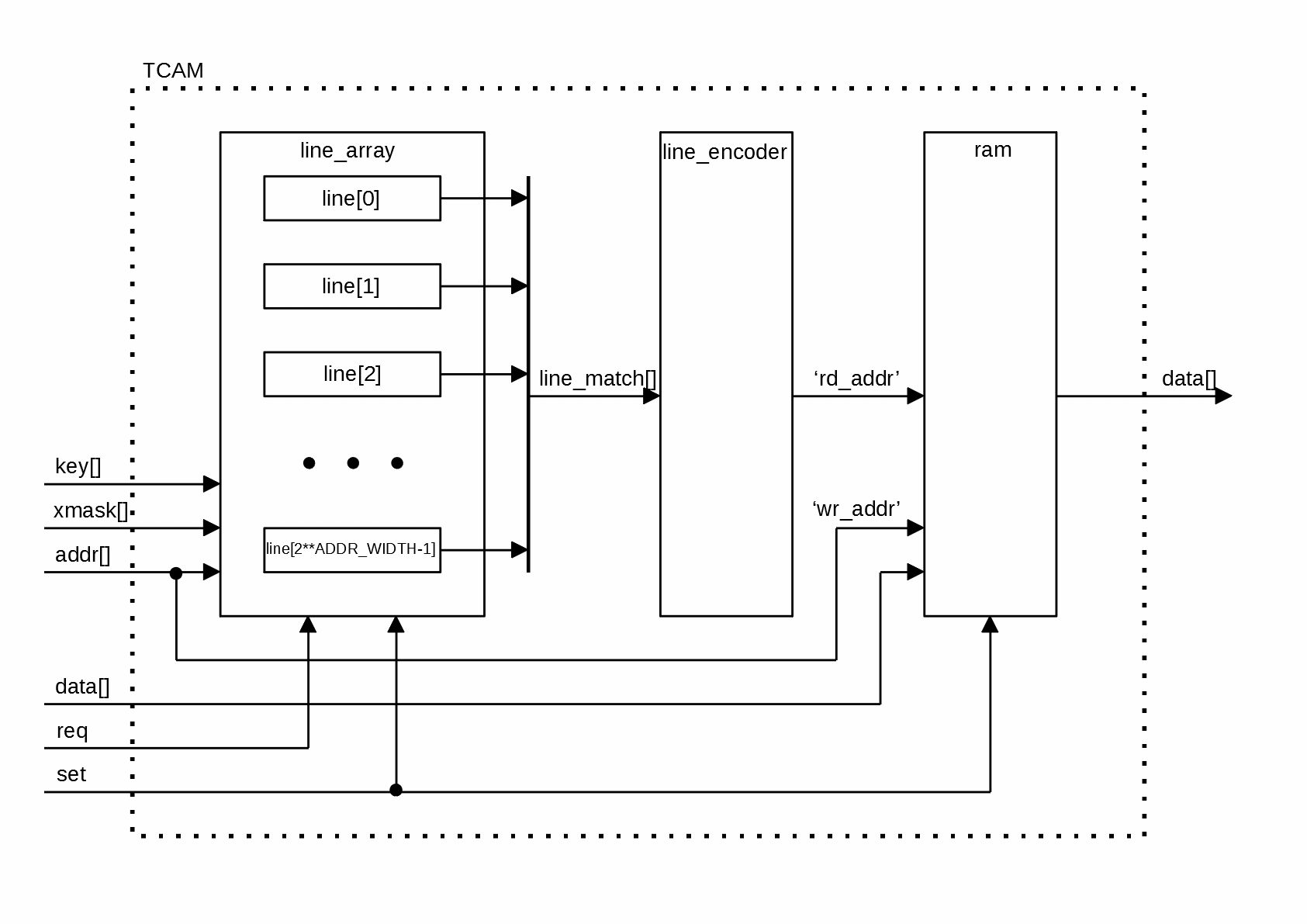
- line_array - array of lines, each line contains registered memory (keys and masks) and matching logic
- line_encoder - converts input line match signals to corresponding addresses sequentially
- ram - random access memory containing data
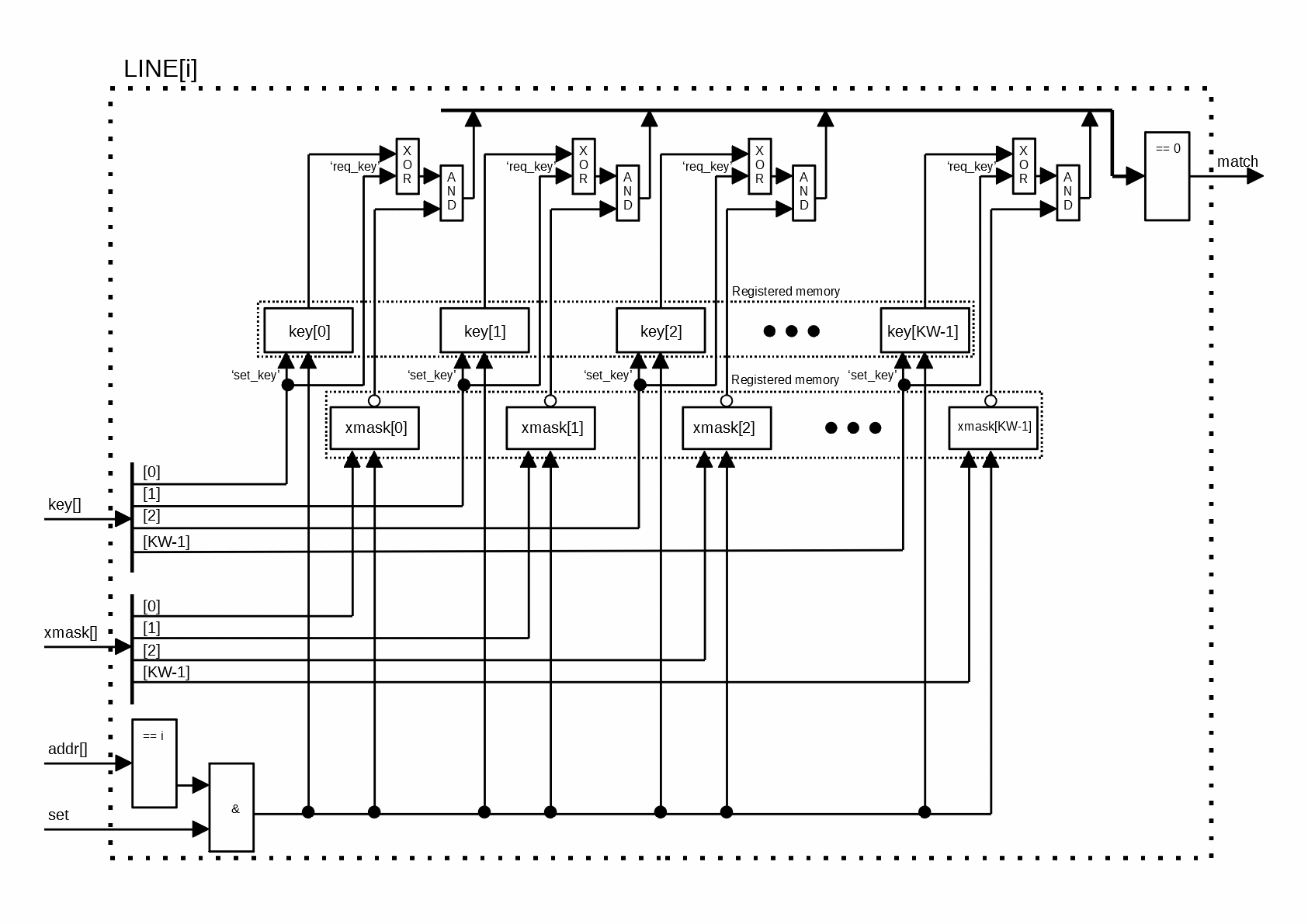
Description:
Each key and mask are contained in the registered memory. This circumstance allows implement parallel matching logic. The output match signal is comparison of zero with results of function: "buffered key" XOR "input request key" AND "inverted buffered mask".


