-
Notifications
You must be signed in to change notification settings - Fork 10
Castor Universal Feedback
#Universal Odometry Feedback System
##Design of an odometry feedback system that works on all the flat terrain. Our bot consists of 4 BLDC motors which have Hall effect sensor built in,this sensors helps us to give the feedback on what's the speed & velocity of the shaft when connected to the normal wheel but since we are using Omni wheels we cannot take the advantage of the Hall effect sensor To overcome this problem we had to design our own feedback system, after lots of brainstorming we had many idea on how our feedback should be, we fabricated 3 designs which had some errors in them on our 4th design we were successful to build an perfect Universal Odometry Feedback system
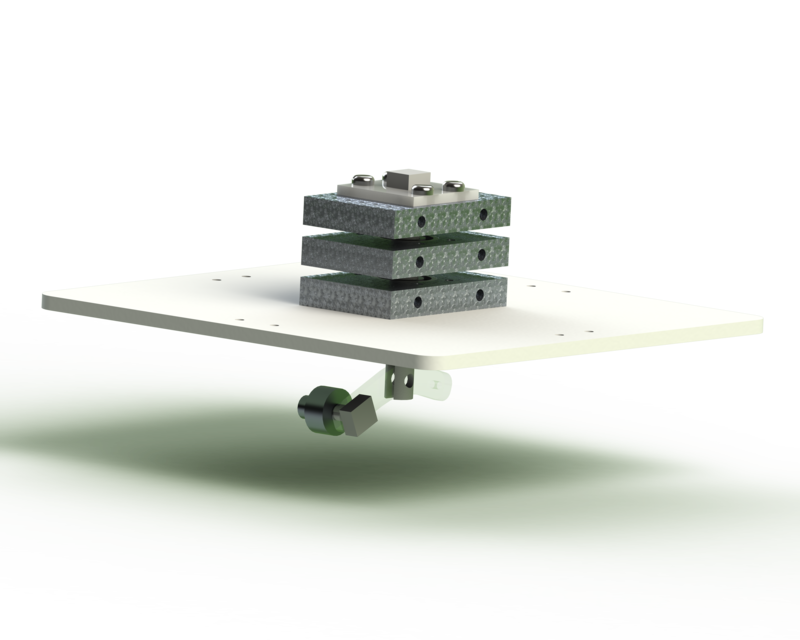
##Design of the Universal Odometry Feedback ###Mechanical The feedback consists of a wheel which is always in contact to the ground,a rotary encoder is connected to the wheel for the feedback of the distance travelled, by converting the circumference of the wheel to linear distance. A Side link is used to attach this wheel and the Encoder shaft. Encoder shaft has 3 holes other than the connecting ones.The 3 wires from the encoder of the wheel go into this shaft and gets connected to 3 different conductive bearing blocks. Conductive bearing blocks are made from aluminium which has bearings in it for the rotation of the blocks with shaft,all 3 blocks are separated by the a foam sheet so avoid short circuit , so the 3 wires from the encoder are connected each block , the whole setup of the encoder shaft with conductive bearings,sidelink and wheel can be rotated and another encoder is used to measure the rotation of the bot.this assembly is made so that the wires from the wheel encoder should not get entangled and get damaged.
###Electrical Wheel encoder consists of 3 pins , 1 pin for ground and 2 for input pins these pins are connected to the 3 Bearing blocks respectively Shaft encoder is also an rotary encoder which has 3 pins.all this 6 pins are connected to arduino via 6 pin connecter.
6th sem, 2017 Batch
Automation and Robotics Dept.
B. V. Bhoomaraddi College of Engineering and Technology, Hubli.
- Introduction
- The Process we went through
- Gantt Chart
- Functional Analysis
- Morphological Chart
- Morphological Chart Revision 2
- [Industrial Standards used](https://github.com/prajankya/Lidar-Robot/wiki/Industrial Standards used)
- [Performance Specification](https://github.com/prajankya/Lidar-Robot/wiki/Performance specification)
- Production Drawings
- [Testing Plan](https://github.com/prajankya/Lidar-Robot/wiki/Testing Plan)
- Work Breakdown Structure
- Bill Of Materials
- Price comparison and Market analysis
- Fabrication
- [Castor Universal Feedback](https://github.com/prajankya/Lidar-Robot/wiki/Castor Universal Feedback)
- Project Invesment
- Revisions
- References
